Draft of a piston-less pressure driven engine
Emin Gabrielyan
Updated on 2010-05-12 ← 2010-05-12
Draft of a piston-less internal combustion engine.
Constant velocity ratio gear engine
Two cogs engaged cycloid gears
Three cogs engaged cycloid gears
Four cogs engaged cycloid gears
Combating sliding and gas leakage
Alternating velocity ratio gear pressure engine
Constant velocity ratio gear engine
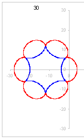
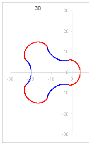
Cycloid gears provide a constant velocity ratio (in contrast to example of the section “Alternating velocity ratio gear pressure engine”). The teeth of such gears have shape of cycloids obtained by rolling (without sliding) an imaginary small circle on a circumference of a main circle. A curve traced by a virtual point fixed on a small circle forms a cycloid. If the small circle rolls outside of the main circle its point will trace an epicycloid and if it rolls inside, the curve will be a hypocycloid.
The below image show an epicicloid (in red) and a hypocycloid (in blue) obtained by rolling a circle of a radius 2 on a circumference of a circle of a radius 12. The red curve is traced by a point of a small circle, when it rolls outside the main circle, and the blue one is traced by its point when it rolls inside.
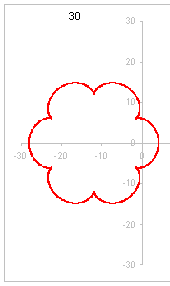
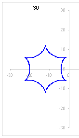
Here are two separate images, the first one showing only the epiciclyoid and the second one only the hypocycloid.
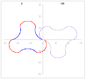
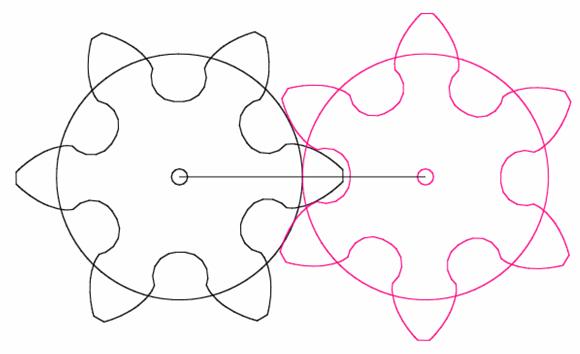
By interleaving the epicycloid with the hypocycloid at their intersection points (on the main circle), we obtain a cycloid gear shape.
Below we show three animations of engaged gears in rotation:
Engaged cycloid gears in rotation with two cogs

Engaged cycloid gears with three cogs
Four-cog cycloid gears

Combating sliding and gas leakage
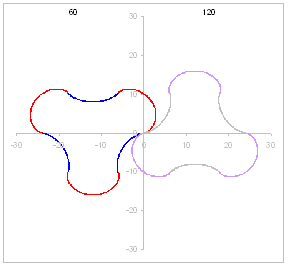
If the mechanical engagement of gears is ensured only by shapes shown above, then a gas leakage cannot be avoided due to a possibility of an independent rotation of one of the gears in wrong direction. The first image below shows a correct engagement of two gears, but in the second image, the 2nd gear (on the right) is rotated by -5 degree with respect to its correct position.

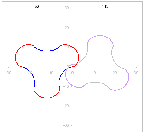
A half cycle later (60 degree rotation of the first gear on the left), such a -5 degree error (of the first gear) is not be possible anymore. The first image below shows a correct engagement at this new position, and the second image shows an attempt of rotation of the 2nd gear by -5 degree (not possible anymore as otherwise shapes must intersect).
This gives us an idea of combining two engagement modes in parallel. The above images represent a top view along the Z axis. As the constant velocity ratio is provided, we can have another engagement in a parallel surface deeper in the Z axis, were the two parallel gears are also engaged correctly, but with the +60 degree rotation of the first (left) gear. The parallel counterparts are fixed on the same rotation axis. Such a double engagement protects from independent sliding of any of the pair. Whenever a negative sliding is possible in the top layer, it is impossible in the bottom layer and visa versa. Again, note that such a parallel layers of gears engaged at different degree is mechanical possible only thanks to the guaranteed constant velocity ratio.
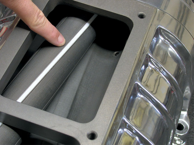
We can imagine also more than 2 layers smoothly changing the rotation degree from 0 to 60 along the Z axis. This shall explain why in the picture below (apparently for a gas counter) the blade looks inclined.
Engaging involute shaped gears
Finally, we can consider also involute shaped engagement.
[ems] (an emachineshop.com file)
I am not sure if it is desirable for this purpose due to a constant friction between teeth.
 [gif]
(taken from http://en.wikipedia.org/wiki/Involute_gear)
[gif]
(taken from http://en.wikipedia.org/wiki/Involute_gear)
References:
http://mysite.du.edu/~etuttle/tech/cycloid.htm
http://en.wikipedia.org/wiki/Cycloid_gear
Keywords:
Blower rotors
Roots blower
http://en.wikipedia.org/wiki/Roots_type_supercharger
Gear pump
http://en.wikipedia.org/wiki/Gear_pump
Supercharger
http://en.wikipedia.org/wiki/Supercharger
* * *
Alternating velocity ratio gear pressure engine
Today, May 12, 2010, 16:51:34
I present here a part of a draft of a piston-less engine. I got this idea first time when was in the school. At that time I had no access to a machine that can manufacture such shape, but now seems a prototype can be created easily with emachineshop.com.
The two 3-thooth cogwheels shown below are to be placed in a chamber with not more than 60 degree opening on one side (page top) for exit of gases and a supply a pressure on the other side (page bottom). This draft is not complete.
There is a sliding problem to be solved. A feasible method would be an extension containing fine granularity gear profile on each (cylindrical shaped) contact surface. A tooth profile offering constant velocity ratio (e.g. cycloid or involute) is to be used. The constant ratio is respected during each of the two cycles with two different ratios. The fine gear profile can be implemented outside the chamber if pressure escape issues may arise.
Sadly, the idea is not revolutionary as the multiple references show below. Testing such a device with emachineshop.com remains a challenge.
References:
http://en.wikipedia.org/wiki/Involute_gear
http://en.wikipedia.org/wiki/Gear
http://en.wikipedia.org/wiki/Cycloid_gear
http://mysite.du.edu/~etuttle/tech/cycloid.htm
Keywords:
Blower rotors
Roots blower
http://en.wikipedia.org/wiki/Roots_type_supercharger
Gear pump
http://en.wikipedia.org/wiki/Gear_pump
* * *