Fast optical indicator created with multi-ring moiré patterns
Emin Gabrielyan
Switzernet.com
Patent Pending
In mechanical measurement devices where measured values are indicated with a mechanical pointer and a graduated scale, the observation precision is increased often by adding an auxiliary mechanical pointer with a sub graduated scale. The auxiliary pointer moves in synchronization with the main pointer but at a higher speed. A constant velocity ratio between the auxiliary pointer and the main pointer is maintained via cogwheel type gearboxes. Mechanical solutions are not always suitable. A challenging idea is to use moiré phenomenon for its well known magnification and acceleration properties. Sharp moiré shapes with good luminosity and contrast can be however obtained only in highly periodic patterns. The periodic nature of patterns makes them inapplicable for indication of values. We present new discrete patterns assembled from simple moiré patterns of different periodicity. The elevation profile of our discrete pattern reveals a joint moiré shape with an arbitrarily long period. The luminosity and the sharpness of our shapes are as high as in simple highly periodic moiré.
Keywords: moiré, instrumentation, metrology, multi-stripe moiré, multi-ring moiré, non-periodic moiré, optical speedup, moiré indicator, moiré pointer, moiré watches, optical clock-hands, moiré clock-hands
Table of contents
Fast optical indicator created with multi-ring moiré patterns
2.1...... Superposition of layers with periodically repeating parallel lines
2.2...... Speedup of movements with moiré
2.3...... Superposition of layers with inclined lines
2.3.1. Computing moiré lines’ inclination as function of the inclination of layers’ lines
2.3.2. Deducing the known formulas from our equations
2.3.3. The revealing lines inclination as a function of the superposition image’s lines inclination
3. Superposition of periodic circular patterns
3.1...... Superposition of circular periodic patterns with radial lines
3.2...... Superposition of circular patterns with radial curves
4. Layer patterns with spirals in a single ring
6. Multi-ring moiré with inclined line patterns
6.1...... Straight radial moiré lines with curved layer lines
6.2...... Curved moiré lines in multi-ring patterns
1. Introduction
A graduated scale and a mechanical pointer is a common part for almost all mechanical measurement devices. Often an auxiliary pointer and a scale with sub graduations are used for additional precisions. The auxiliary pointer moves faster, in synchronization with the main pointer. The pointers are connected via a tooth wheel type transmission system. The involute tooth shape is one that results in a constant velocity ratio, and is the most commonly used in instrumentation gearing, clocks and watches. Mechanical methods for changing the speed however can often be heavy and inapplicable. Lack of the force, such as in a compass, can be one of the serious obstacles. Inertia problems arising from discrete movements of mechanical parts at high speed, such as in chronographs, may be another obstacle.
The magnification and acceleration properties of moiré superposition images are a well known phenomenon. The superposition of transparent structures, comprising periodic opaque patterns, forms periodic moiré patterns. A challenging idea would be to use optical moiré effect for creating a fast auxiliary pointer replacing completely the mechanical parts moving at high speeds. The periodic nature of known moiré patterns make them inappropriate for indication of values. Profiles with very long periods can be created with periodic moiré. It is possible to design circular layer patterns with radial lines such that their superposition produces a radial moiré fringe with an angular period equal to 360 degrees. Thus only single radial moiré fringe will be visible in the superposition pattern. However such long periods make the moiré fringes blurred. The dispersion area of the fringe can be as large as the half of the period. In section 4 we show a particular case where a radial periodic moiré can be of use with an additional design extension. However in general, the long period moiré fringes of classical periodic moiré are too inexact for indication purposes.
A limited degree of sharpening of shapes in periodic moiré is possible using band moiré methods, namely moiré magnification of micro shapes [Hutley99], [Kamal98]. Such shapes however require serious sacrifices of the overall luminosity of the superposition image without significant improvements of the sharpness.
Random moiré, namely Glass patterns, produce non-periodic superposition patterns [Amidror03a], [Amidror03b], [Glass69a], [Glass73a]. The obstacle is that the valid range of movements of layers is very limited. The auxiliary indicator would show the sub graduations only within the range of only one graduation of the main scale. Additionally, in random moiré the shapes are noisier than in simple periodic moiré.
We developed new discrete patterns formed by merging straight stripes or circular rings of simple periodic moiré patterns. The composing stripes or rings are simple patterns with carefully chosen periods and phases. The composite pattern reveals a sharp moiré shape with an arbitrarily long periodicity. Movement of a layer along the stripes or along the circumferences of rings produces a faster movement of the moiré shape. Such shape has all qualities for playing the role of the fast auxiliary indicator. The one of the layers can be put into slow mechanical motion by the main pointer of the measurement device. In our discrete patterns the shapes are as sharp as in highly periodic moiré patterns. The period of the moiré pointer can be as long as it is required by the display size of the instrument. In our discrete patterns, the choice of the period has no impact on the quality of the optical shape and a wide range of speed ratios can be obtained.
Choice of stripes or rings depends on the type of the movement of layers. For linear movements the pattern comprises parallel stripes following the path of the movement. For circular movements the pattern consists of concentric rings with a center corresponding to the rotation axis. Our algorithm merges numerous simple periodic patterns into a composite pattern so as to form a continuous joint shape in the assembled superposition image. The underlying layer patterns do not join into continuous shapes within assembled layers. The composite patterns are constructed, such that the velocity ratios across all individual moiré patterns are identical. Consequently, the joint shape of the multi-stripe or multi-ring moiré pattern conserves its form during movements of the optical image. The speed ratio and the sharpness of moiré shape are constant within the full range of movements of the main pointer and layers.
Circular multi-ring samples are the most interesting. They can be used for adding auxiliary optical pointers to numerous measurement device with circular dials and radial mechanical pointers such as clocks, watches, chronographs, protractors, thermometers, altimeters, barometers, compasses, speedometers, alidades, and even weathervanes. In mechanical chronographs, optical acceleration permits measuring fractions of seconds without having mechanical parts moving at high speed with related problems of force, inertia, stress, and wear.
The paper is organized as follows. Section 2 introduces the classical periodic moiré and the methods for forming periodic moiré fringes of a desired shape. These methods are presented in scope of a new perspective for easily changing the curves of moiré shapes without affecting the periodicity and the velocity ratios, which are essential parameters for the metrology purposes. Linear movements are considered and a set of corresponding equations is introduced. Section 3 introduces the equations for creating curved moiré shapes for rotating layers preserving the angular periodicity and velocity ratio. Section 4 presents an application of classical moiré. In sections 4 and 5 we present multi-ring moiré with various curved layer patterns and moiré superposition patterns. The conclusions are presented in section 7.
2. Simple moiré patterns
2.1. Superposition of layers with periodically repeating parallel lines
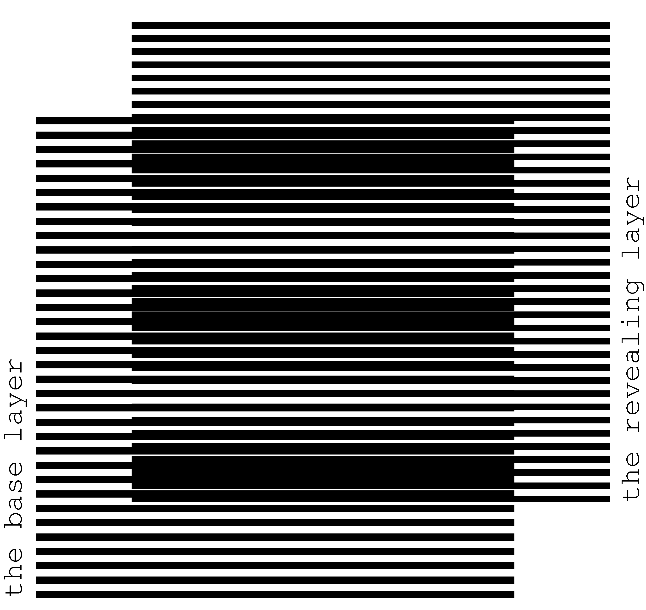
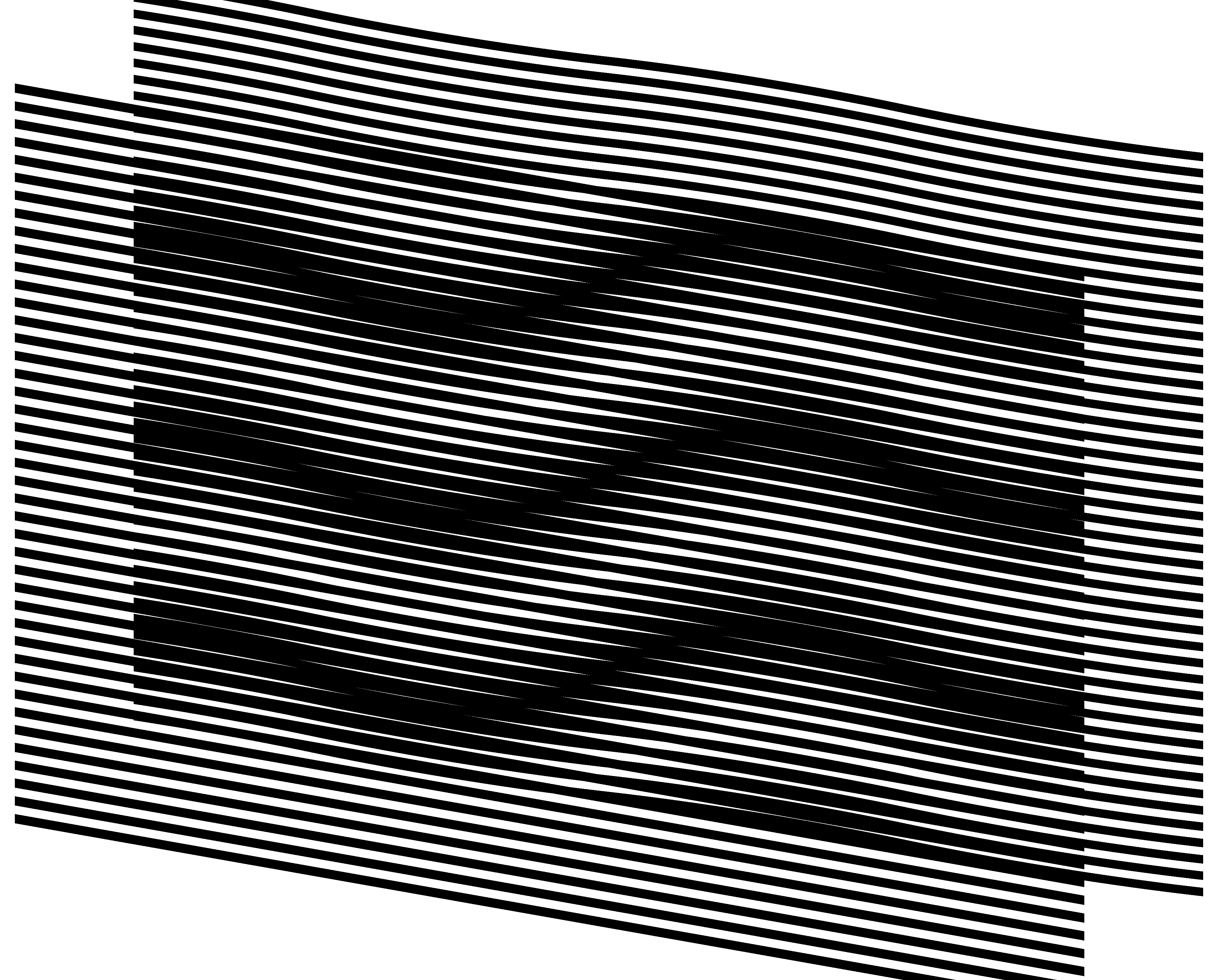
Simple moiré patterns can be observed when superposing two transparent layers comprising periodically repeating opaque parallel lines as shown in Figure 1. The lines of one layer are parallel to the lines of the second layer.
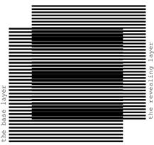
Figure 1. Superposition of two layers consisting of parallel lines, where the lines of the revealing layer are parallel to the lines of the base layer [eps], [tif], [png]
The superposition image does not change if the
transparent layers with their opaque patterns are inverted. We denote one of
the layers as the base layer and the other one as the revealing layer.
When considering printed samples we assume that the revealing layer is printed
on a transparency and is superposed on top of the base layer, which can be
printed either on a transparency or on an opaque paper. The periods of the two layer
patterns, i.e. the space between the axes of parallel lines, are close. We
denote the period of the base layer as ![]() and
the period of the revealing layer as
and
the period of the revealing layer as ![]() . In Figure 1,
the period of lines of the base layer is equal to 6 units, and the period of
lines of the revealing layer is equal to 5.5 units.
. In Figure 1,
the period of lines of the base layer is equal to 6 units, and the period of
lines of the revealing layer is equal to 5.5 units.
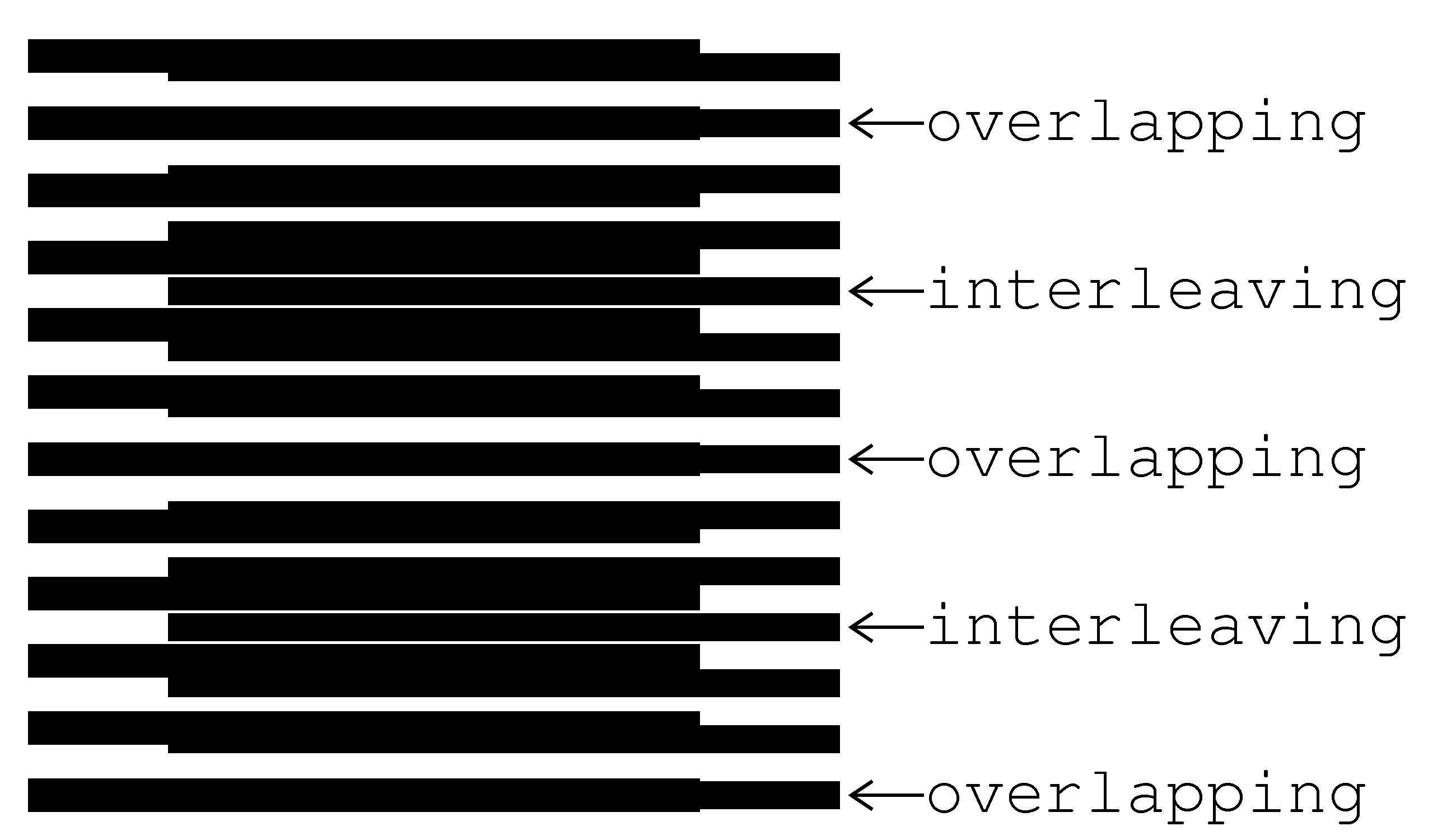
The superposition image of Figure 1 outlines periodically repeating dark parallel bands, called moiré lines. Spacing between the moiré lines is much larger than the periodicity of lines in the layers.
Light areas of the superposition image correspond to the zones where the lines of both layers overlap. The dark areas of the superposition image forming the moiré lines correspond to the zones where the lines of the two layers interleave, hiding the white background. The labels of Figure 2 point on periodically interchanging light and dark bands. The light bands are formed due to overlapping layer lines, and the dark bands due to interleaving layer lines.

Figure 2. Superposition of two layers consisting of horizontal parallel lines [eps], [png]
Figure 3 shows a detailed diagram of the superposition image between two light zones, where the lines of the revealing and base layers overlap [Sciammarella62a, p.584].
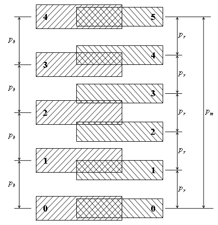
Figure 3. Computing the period of moiré lines in a superposition image as a function of the periods of lines of the revealing and base layers
The period ![]() of
moiré lines is the distance from one point where the lines of both layers
overlap (at the bottom of the figure) to the next such point (at the top). Let
us count the layer lines, starting from the point where they overlap. Since in
our case
of
moiré lines is the distance from one point where the lines of both layers
overlap (at the bottom of the figure) to the next such point (at the top). Let
us count the layer lines, starting from the point where they overlap. Since in
our case ![]() , for the same number of counted
lines, the base layer lines with a long period advance faster than the revealing
layer lines with a short period. At the halfway of the distance
, for the same number of counted
lines, the base layer lines with a long period advance faster than the revealing
layer lines with a short period. At the halfway of the distance ![]() , the base layer lines are ahead the
revealing layer lines by a half a period (
, the base layer lines are ahead the
revealing layer lines by a half a period (![]() )
of the revealing layer lines, due to which the lines are interleaving, forming a
dark zone. At the full distance
)
of the revealing layer lines, due to which the lines are interleaving, forming a
dark zone. At the full distance ![]() , the base
layer lines are ahead of the revealing layer lines by a full period
, the base
layer lines are ahead of the revealing layer lines by a full period ![]() , so the lines of the layers again overlap.
The base layer lines gain the distance
, so the lines of the layers again overlap.
The base layer lines gain the distance ![]() with
as many lines (
with
as many lines (![]() ) as the number of the
revealing layer lines (
) as the number of the
revealing layer lines (![]() ) for the same
distance minus one:
) for the same
distance minus one:
From equation (2.1) we obtain the well known formula for the period ![]() of
the superposition image [Amidror00a p.20]:
of
the superposition image [Amidror00a p.20]:
The superposition of two layers comprising parallel lines forms an optical image comprising parallel moiré lines with a magnified period. According to equation (2.2), the closer the periods of the two layers, the stronger the magnification factor is.
If the numbers ![]() and
and
![]() are
integers, then if at some moiré light zone the lines of both layers perfectly
overlap, as shown in Figure 3, the layer lines will also perfectly overlap also
at the centers of each other light zone. If
are
integers, then if at some moiré light zone the lines of both layers perfectly
overlap, as shown in Figure 3, the layer lines will also perfectly overlap also
at the centers of each other light zone. If ![]() and
and
![]() are not integers, then the centers of
white moiré zones do not necessarily match with the centers of layer lines. In
any case, equation (2.2) remains valid.
are not integers, then the centers of
white moiré zones do not necessarily match with the centers of layer lines. In
any case, equation (2.2) remains valid.
For the case when the revealing layer period is longer than the base layer period, the space between moiré lines of the superposition pattern is the absolute value of formula of (2.2).
The thicknesses of layer lines affect the
overall darkness of the superposition image and the thickness of the moiré
lines, but the period ![]() does not depend on
the layer lines’ thickness. In our examples the base layer lines’ thickness is
equal to
does not depend on
the layer lines’ thickness. In our examples the base layer lines’ thickness is
equal to ![]() , and the revealing layer lines’
thickness is equal to
, and the revealing layer lines’
thickness is equal to ![]() .
.
2.2. Speedup of movements with moiré
The moiré bands of Figure 1 will move if we
displace the revealing layer. When the revealing layer moves perpendicularly to
layer lines, the moiré bands move along the same axis, but several times faster
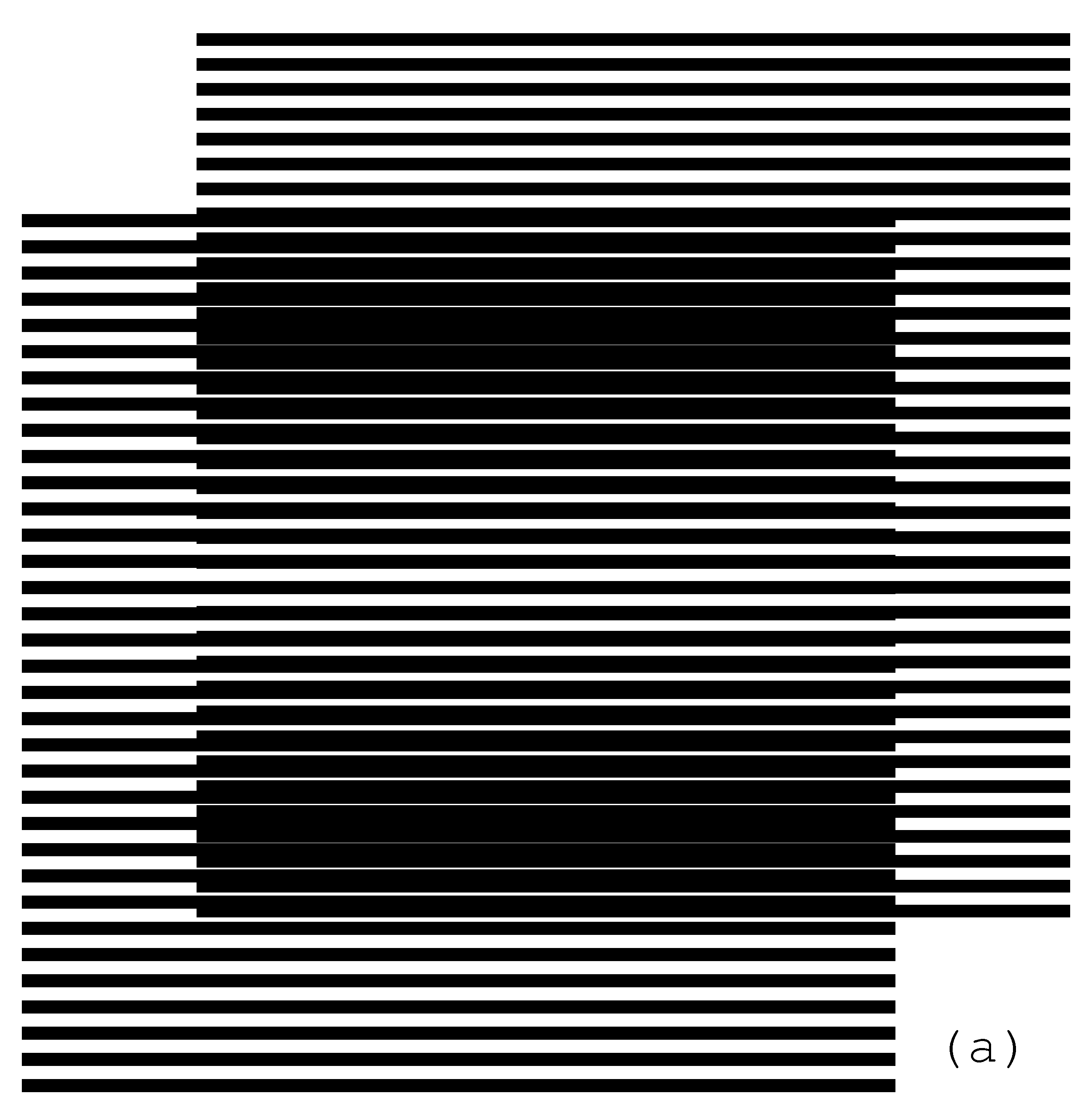
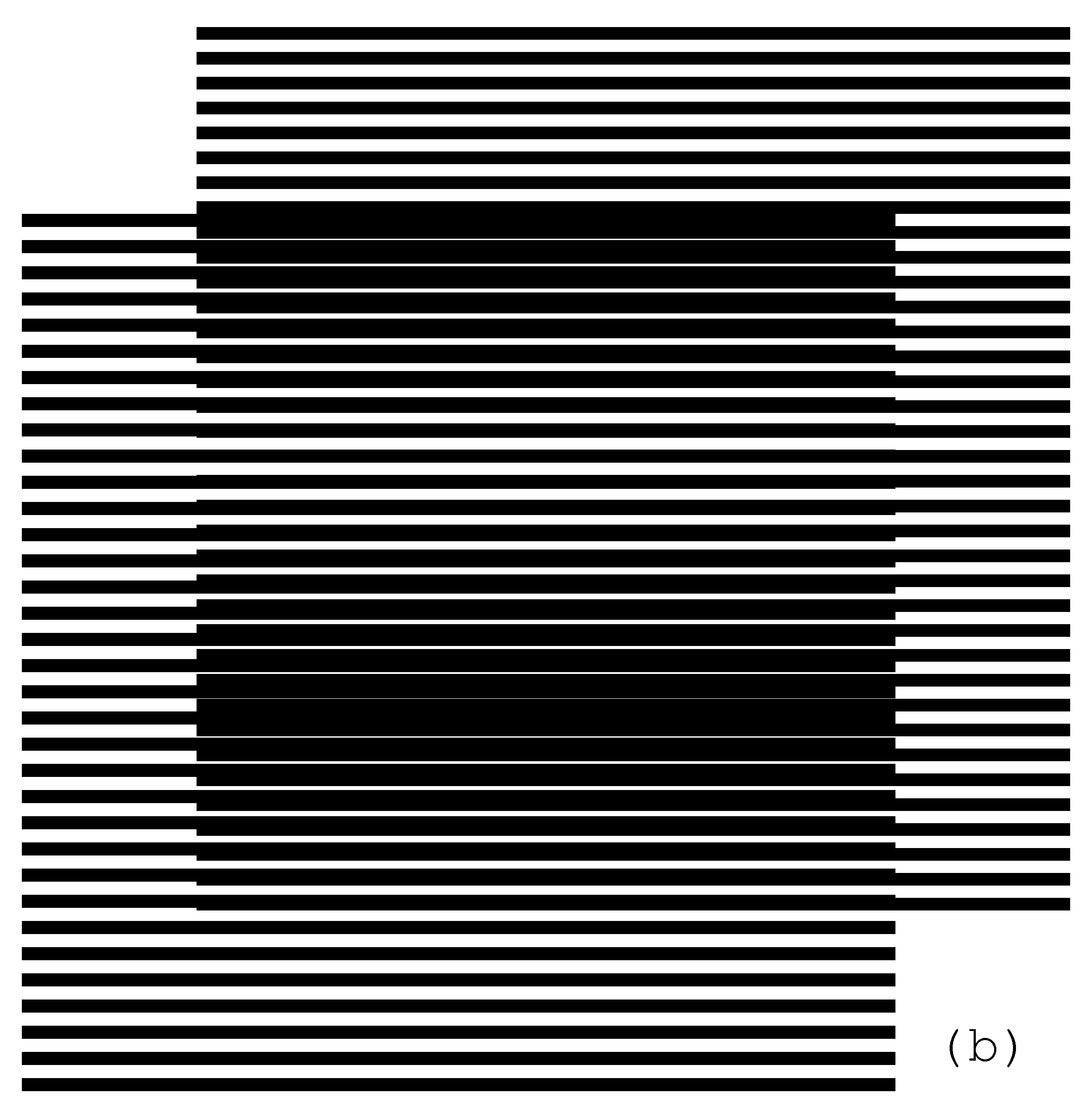
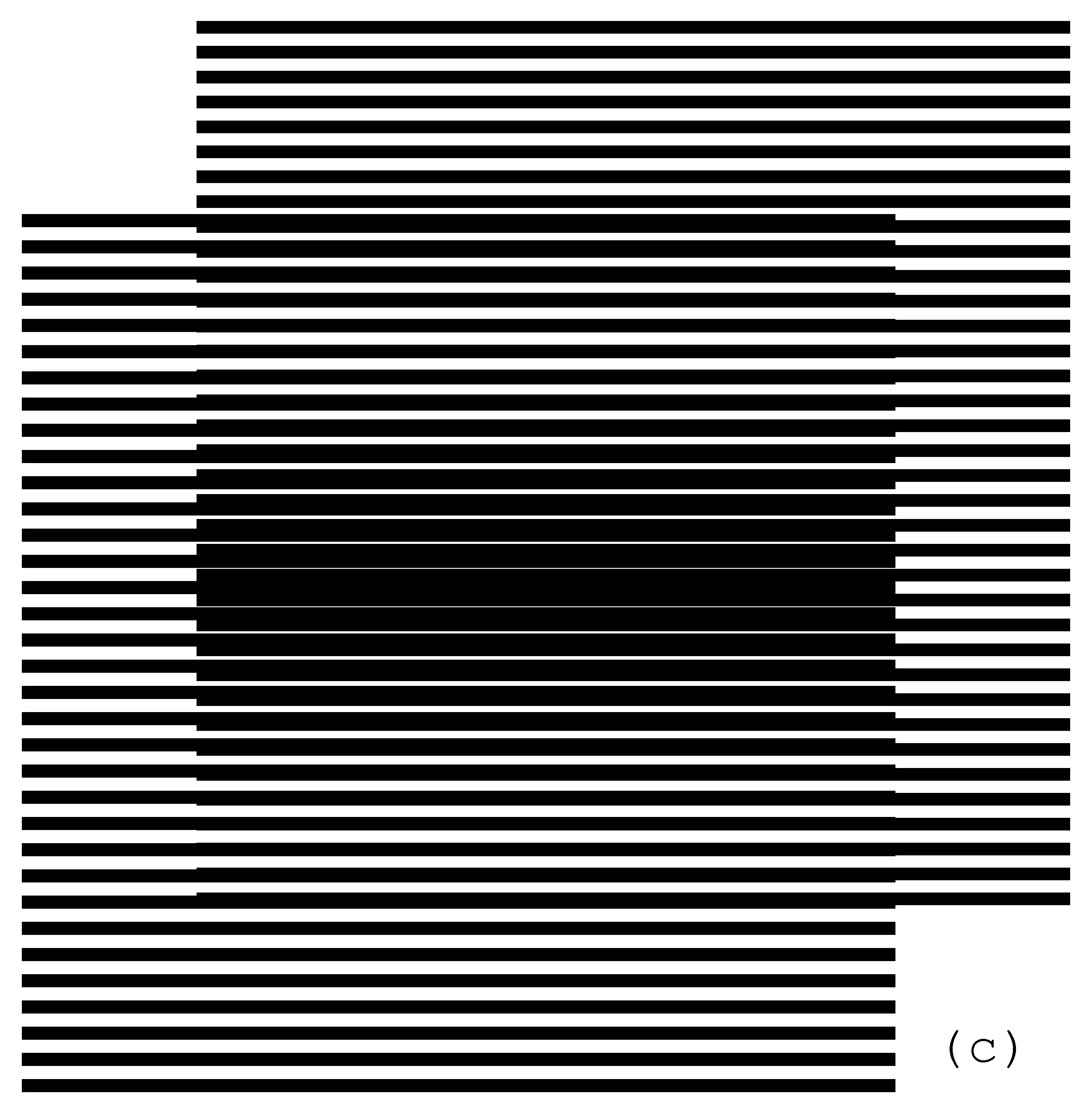
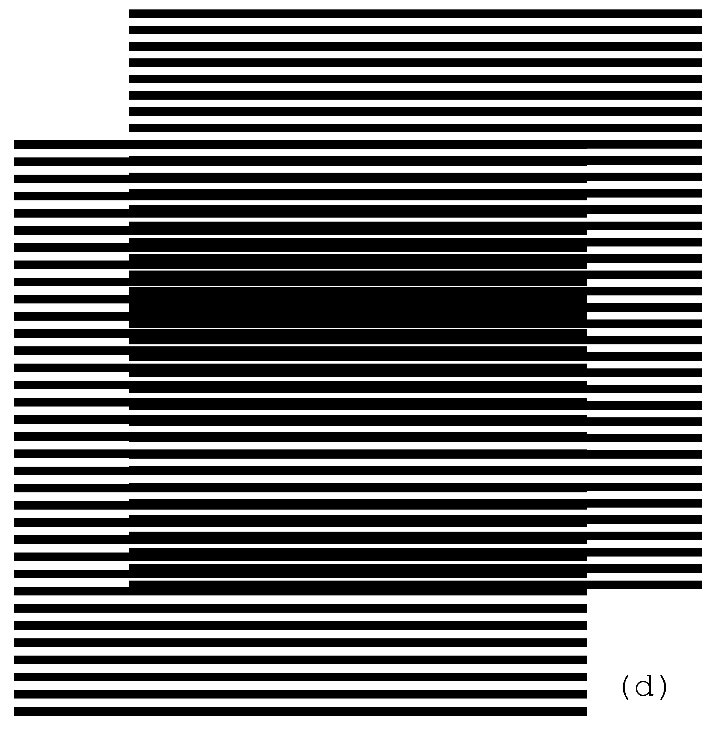
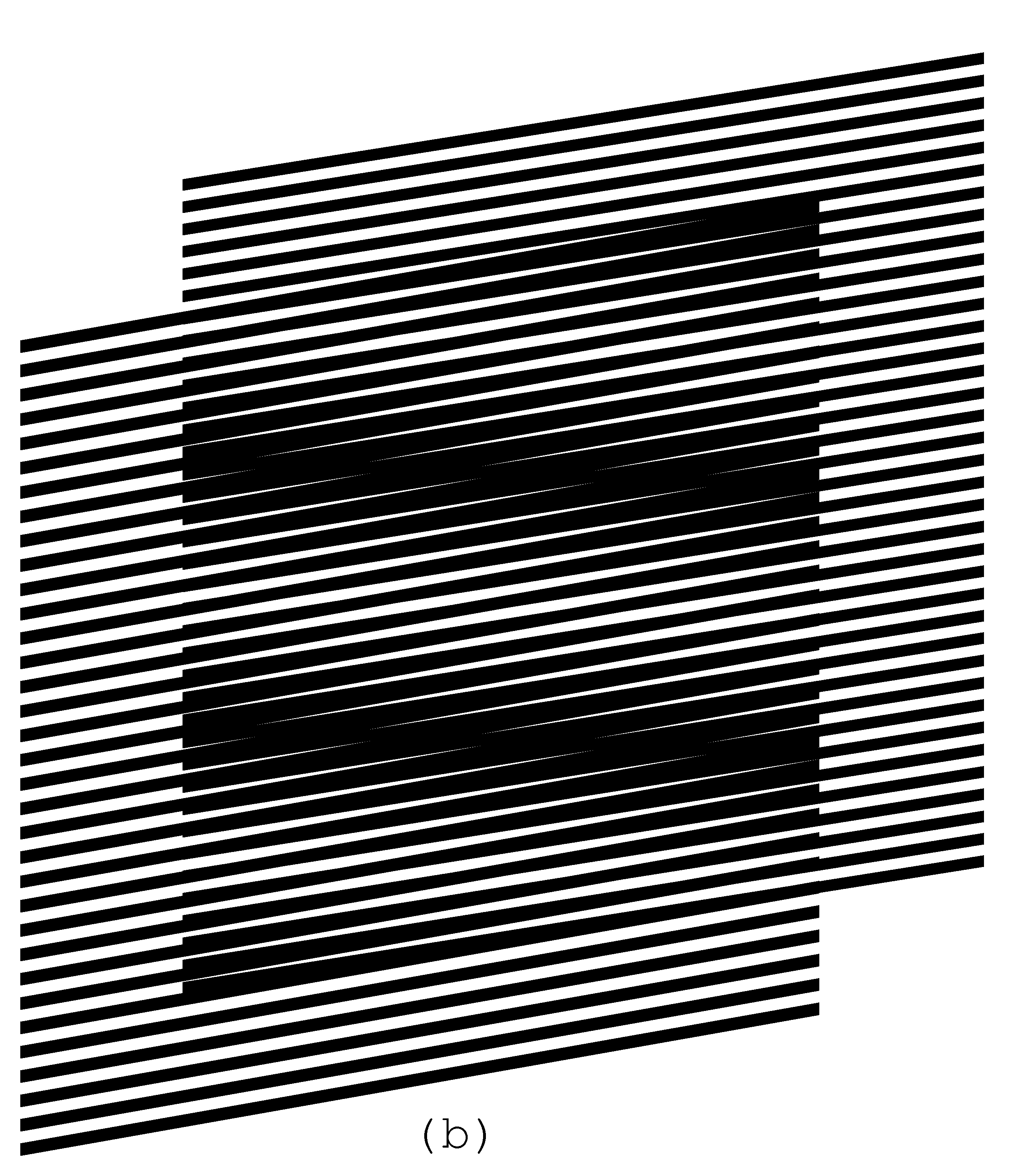
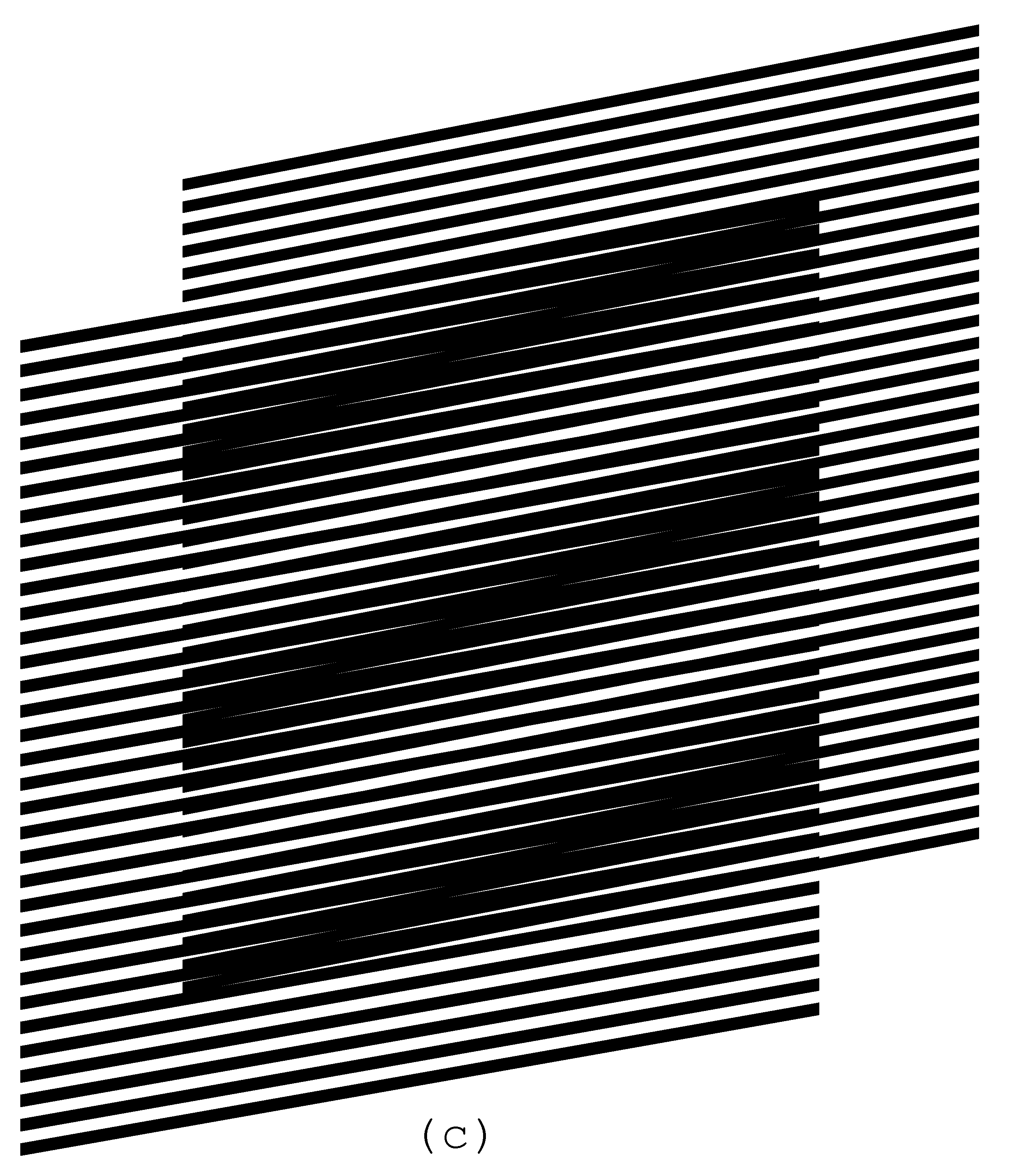
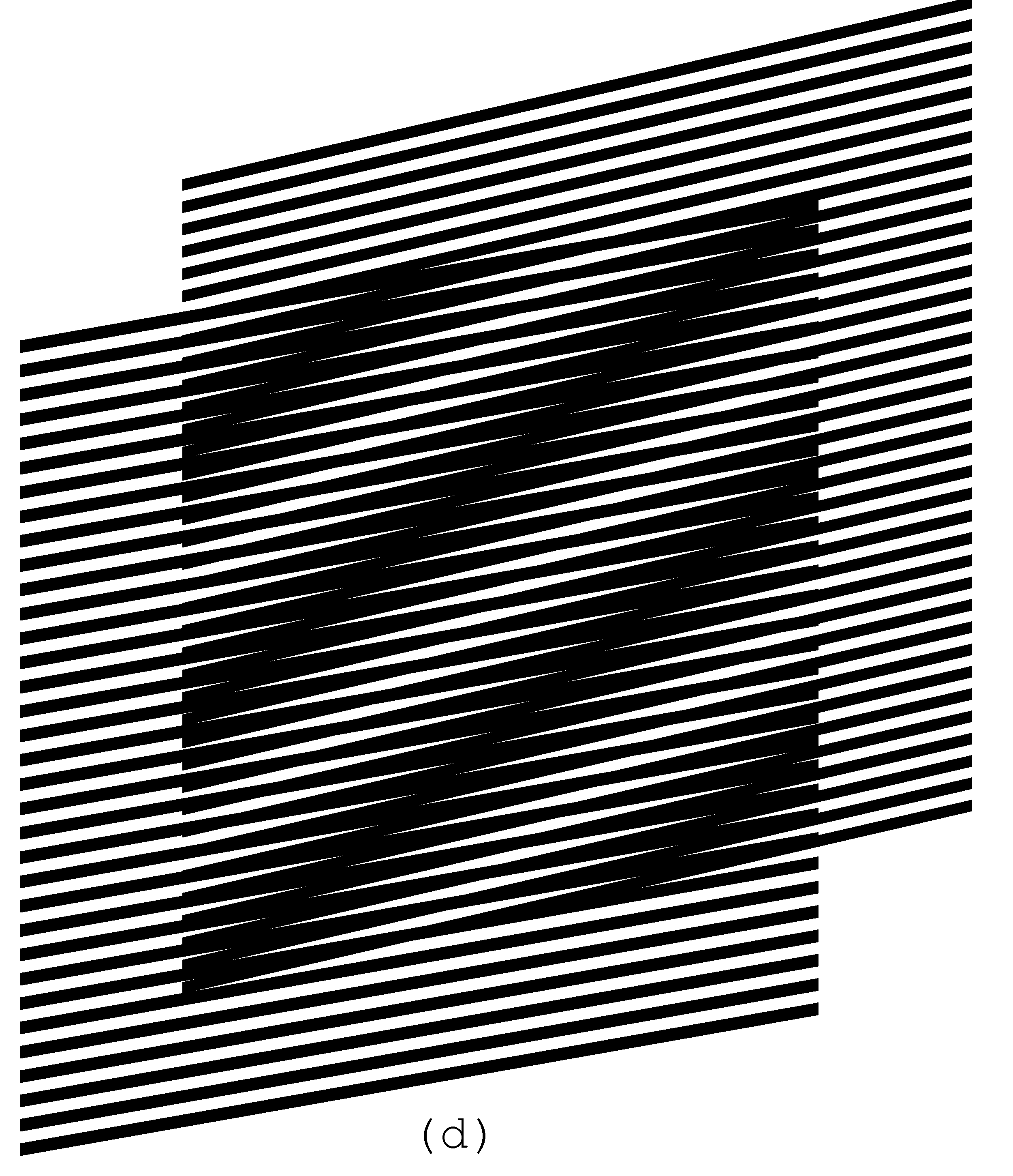
than the movement of the revealing layer. The four images of Figure 4 show the
superposition image for different positions of the revealing layer. The base
layer period is equal to 6 units and the revealing layer period is 5.7 units. Compared
with the first image (a) of Figure 4, in the second image (b) the revealing
layer is shifted up by one fourth of the revealing layer period (![]() ), in the third image (c) the revealing
layer is shifted up by half of the revealing layer period (
), in the third image (c) the revealing
layer is shifted up by half of the revealing layer period (![]() ), and in the fourth image (d) the
revealing layer is shifted up by three fourth of the revealing layer period (
), and in the fourth image (d) the
revealing layer is shifted up by three fourth of the revealing layer period (![]() ). The images show that the moiré lines
of the superposition image move up at a speed, much faster than the speed of
movement of the revealing layer.
). The images show that the moiré lines
of the superposition image move up at a speed, much faster than the speed of
movement of the revealing layer.
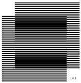
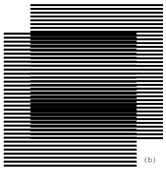
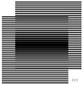
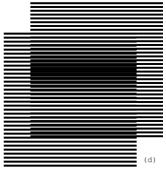
Figure 4. Superposition of two layers with parallel horizontal lines, where the revealing layer moves vertically at a slow speed [eps (a)], [png (a)], [eps (b)], [png (b)], [eps (c)], [png (c)], [eps (d)], [png (d)]
When the revealing layer is shifted up
perpendicularly to the layer lines by one full period ![]() of its pattern, the superposition optical
image must be the same as the initial one. It means that the moiré lines
traverse a distance equal to the period of the superposition image
of its pattern, the superposition optical
image must be the same as the initial one. It means that the moiré lines
traverse a distance equal to the period of the superposition image ![]() , while the revealing layer traverses the
distance equal to its period
, while the revealing layer traverses the
distance equal to its period ![]() . Assuming
that the base layer is immobile (
. Assuming
that the base layer is immobile (![]() ), the
following equation holds for the ratio of the optical image’s speed to the
revealing layer’s speed:
), the
following equation holds for the ratio of the optical image’s speed to the
revealing layer’s speed:
According to equation (2.2) we have:
In case the period of the revealing layer is longer than the period of the base layer, the optical image moves in the opposite direction. The negative value of the ratio computed according to equation (2.4) signifies the movement in the reverse direction.
The GIF animation of the superposition image corresponding
to a slow movement of the revealing layer is provided in Figure 5. The GIF file
repeatedly animates a perpendicular movement of the revealing layer across a
distance equal to ![]() .
.
Figure 5. GIF animation of the slow vertical movement of the revealing layer [ps], [gif], [tif]
2.3. Superposition of layers with inclined lines
In this section we develop equations for
patterns with inclined lines. When we are interested in optical speedup we can
represent the case of inclined patterns such that the formulas for computing
moiré periods and optical speedups remain valid in their current simplest form.
For this purpose, the periods ![]() ,
, ![]() , and
, and ![]() are
defined so as to correspond to the distances between the lines along the axis
of movements (the vertical axis in the examples of Figure 4 and Figure 5). In
such a way equations (2.2), (2.3), and (2.4) remain valid also for inclined
lines. The periods (p) are equal to the distances (denoted as T)
between the lines, only when the lines are perpendicular to the movement axis
(as in Figure 4 and Figure 5).
are
defined so as to correspond to the distances between the lines along the axis
of movements (the vertical axis in the examples of Figure 4 and Figure 5). In
such a way equations (2.2), (2.3), and (2.4) remain valid also for inclined
lines. The periods (p) are equal to the distances (denoted as T)
between the lines, only when the lines are perpendicular to the movement axis
(as in Figure 4 and Figure 5).
In this section we present equations for computing
inclination angles relying on periods ![]() ,
,
![]() , and
, and ![]() along
the axis of movements. For rotational movements the p values represent
the periods along circumference, i.e. the angular periods.
along
the axis of movements. For rotational movements the p values represent
the periods along circumference, i.e. the angular periods.
2.3.1. Computing moiré lines’ inclination as function of the inclination of layers’ lines
The superimposition of two layers with
identically inclined lines forms moiré lines inclined at the same angle. Figure
6 is obtained from Figure 1 with a vertical shearing. In Figure 6 the layer
lines and the moiré lines are inclined by 10 degrees. Inclination is not a
rotation. During the inclination the distance between the layer lines along the
vertical axis (p) is conserved, but the true distance T between
the lines (along an axis perpendicular to these lines) changes. The difference
between the vertical periods ![]() and
and ![]() , and the distances
, and the distances ![]() and
and ![]() is
shown in the diagram of Figure 10.
is
shown in the diagram of Figure 10.
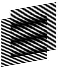
Figure 6. Superposition of layers consisting of inclined parallel lines where the lines of the base and revealing layers are inclined at the same angle [eps], [png]
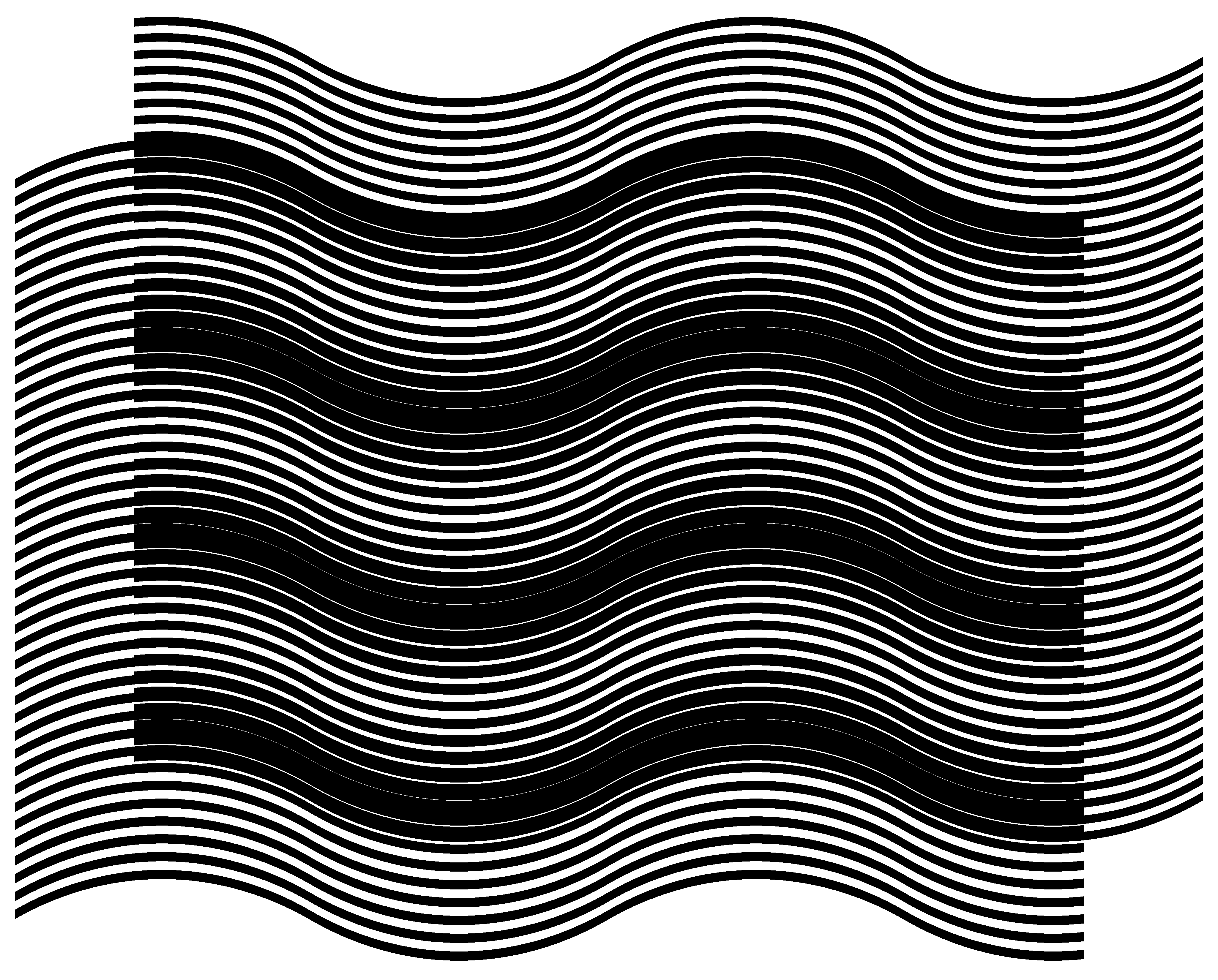
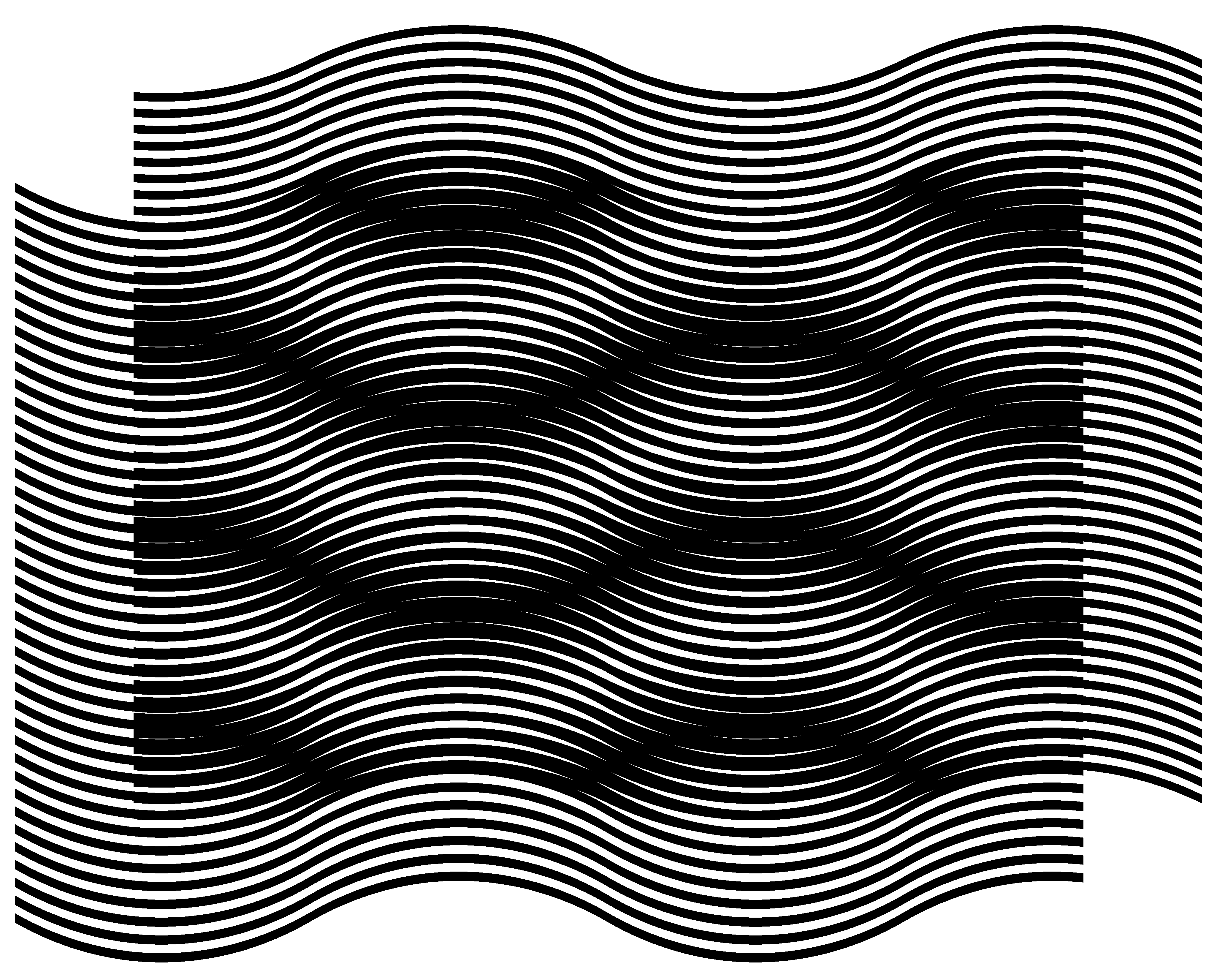
The inclination degree of layer lines may change
along the horizontal axis forming curves. The superposition of two layers with
identical inclination pattern forms moiré curves with the same inclination
pattern. In Figure 7 the inclination degree of layer lines gradually changes
according the following sequence of degrees (+30, –30, +30, –30, +30), meaning
that the curve is divided along the horizontal axis into four equal intervals and
in each such interval the curve’s inclination degree linearly changes from one
degree to the next according to the sequence of five degrees. Layer periods ![]() and
and ![]() represent
the distances between the curves along the vertical axis. In Figure 6 and Figure
7,
represent
the distances between the curves along the vertical axis. In Figure 6 and Figure
7, ![]() is equal to 6 units and
is equal to 6 units and ![]() is 5.5. units. Figure 7 can be obtained
from Figure 1 by interpolating the image along the horizontal axis into
vertical bands and by applying a corresponding vertical shearing and shifting to
each of these bands. Equation (2.2) is valid for computing the spacing
is 5.5. units. Figure 7 can be obtained
from Figure 1 by interpolating the image along the horizontal axis into
vertical bands and by applying a corresponding vertical shearing and shifting to
each of these bands. Equation (2.2) is valid for computing the spacing ![]() between the moiré curves along the
vertical axis and equation (2.4) for computing the optical speedup ratio when
the revealing layer moves along the vertical axis.
between the moiré curves along the
vertical axis and equation (2.4) for computing the optical speedup ratio when
the revealing layer moves along the vertical axis.
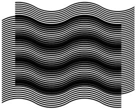
Figure 7. Two layers consisting of curves with identical inclination patterns, and the superposition image of these layers [eps], [png]
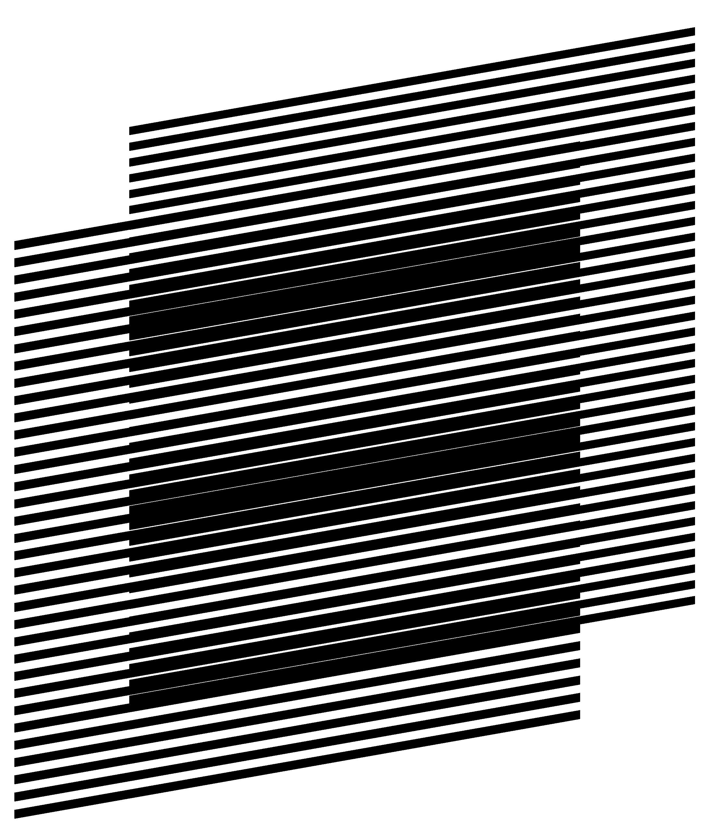
More interesting is the case when the inclination degrees of
layer lines are not the same for the base and revealing layers. Figure 8 shows four superposition images where the inclination
degree of base layer lines is the same for all images (10 degrees), but the inclination
of the revealing layer lines is different for images (a), (b), (c), and (d) and
is equal to 7, 9, 11, and 13 degrees correspondingly. The periods of layers
along the vertical axis ![]() and
and ![]() (6 and 5.5 units correspondingly) are
the same for all images. Correspondingly, the period
(6 and 5.5 units correspondingly) are
the same for all images. Correspondingly, the period ![]() computed with formula (2.2) is also the
same for all images.
computed with formula (2.2) is also the
same for all images.
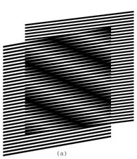
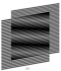
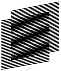
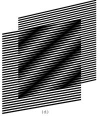
Figure 8. Superposition of layers consisting of inclined parallel lines, where the base layer lines’ inclination is 10 degrees and the revealing layer lines’ inclination is 7, 9, 11, and 13 degrees [eps (a)], [png (a)], [eps (b)], [png (b)], [eps (c)], [png (c)], [eps (d)], [png (d)]
The GIF animation of Figure 9 shows the superposition image when the revealing layer’s inclination oscillates between 5 and 15 degrees:

Figure 9. GIF animation, where the inclination of parallel lines of the revealing layer oscillates between 5 and 15 degrees [ps], [gif], [tif]
Figure 10 helps to compute the inclination degree
of moiré optical lines as a function of the inclination of the revealing and
the base layer lines. We draw the layer lines schematically without showing
their true thicknesses. The bold lines of the diagram inclined by ![]() degrees are the base layer lines. The bold
lines inclined by
degrees are the base layer lines. The bold
lines inclined by ![]() degrees are the
revealing layer lines. The base layer lines are vertically spaced by a distance
equal to
degrees are the
revealing layer lines. The base layer lines are vertically spaced by a distance
equal to ![]() , and the revealing layer lines
are vertically spaced by a distance equal to
, and the revealing layer lines
are vertically spaced by a distance equal to ![]() .
The distance
.
The distance ![]() between the base layer lines
and the distance
between the base layer lines
and the distance ![]() between the revealing
layer lines are not used for the development of our equations. The
intersections of the lines of the base and the revealing layers (marked in the
figure by two arrows) lie on a central axis of a light moiré band between dark
moiré lines. The dashed line of Figure 10 corresponds to the axis of the light moiré
band between two moiré lines. The inclination degree of moiré lines is
therefore the inclination
between the revealing
layer lines are not used for the development of our equations. The
intersections of the lines of the base and the revealing layers (marked in the
figure by two arrows) lie on a central axis of a light moiré band between dark
moiré lines. The dashed line of Figure 10 corresponds to the axis of the light moiré
band between two moiré lines. The inclination degree of moiré lines is
therefore the inclination ![]() of the dashed
line.
of the dashed
line.
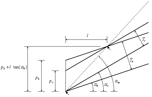
Figure 10. Computing the inclination angle of moiré lines as a function of inclination angles of the base layer and revealing layer lines
From Figure 10 we deduce the following two equations:

From these equations we deduce the equation for computing the inclination of moiré lines as a function of the inclinations of the base layer and the revealing layer lines:
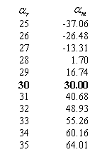
Table 1 shows the moiré lines’ inclinations for several degrees of the revealing layer inclination, for the base layer inclination fixed to 30 degree, with a base layer period equal to 6 units, and with a revealing layer period equal to 5.5 units. The table shows that when the inclination of the lines of the revealing layer is the same as the inclination of the lines of the base layer, the inclination of moiré lines is also identical to the layer lines’ inclination.
Table 1. Inclinations of moiré lines of the superposition image for the base layer lines inclination equal to 30 degrees and for the revealing layer lines inclination from 25 to 35 degrees:
For the same set of parameters, the bold curve of Figure 11 represents the moiré line inclination degree as a function of the revealing layer line inclination. The two other curves correspond to cases, when the base layer inclination is equal to 20 and 40 degrees correspondingly. The circle marks correspond to the points where both layers’ lines inclinations are equal, and the moiré lines inclination also become the same.
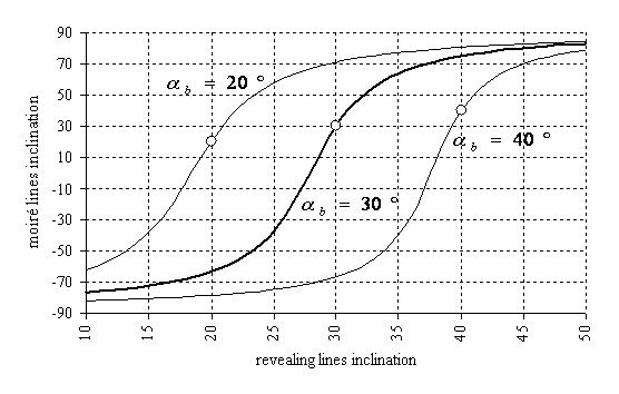
Figure 11. Moiré lines inclination as a function of the revealing layer lines inclination for the base layer lines inclination equal to 30 degrees [xls]
2.3.2. Deducing the known formulas from our equations
The periods ![]() ,
, ![]() , and
, and ![]() used
in the literature are computed as follows (see Figure 10):
used
in the literature are computed as follows (see Figure 10):
|
|
From here, using equation (2.6) we deduce the well known formula for the angle of moiré lines [Amidror00a]:

Recall from trigonometry the following simple formulas:
From equations (2.8) and (2.9) we have:


From equations (2.2) and (2.7) we have:
From equations (2.10) and (2.11) we deduce the
second well known formula for the period ![]() of
moiré lines:
of
moiré lines:

Recall from trigonometry that:
In the particular case when ![]() , taking in account equation (2.13),
equation (2.12) is further reduced into well known formula:
, taking in account equation (2.13),
equation (2.12) is further reduced into well known formula:

Still for the case when ![]() , we can temporarily assume that all
angles are relative to the base layer lines and rewrite equation (2.8) as follows:
, we can temporarily assume that all
angles are relative to the base layer lines and rewrite equation (2.8) as follows:

Recall from trigonometry that:
Therefore from equations (2.15) and (2.16):
|
|
(2.17) |
Now for the case when the revealing layer lines do not represent the angle zero:
|
|
(2.18) |
We obtain the well known formula [Amidror00a]:
Equations (2.8) and (2.12) are the general case
formulas known in the literature, and equations (2.14) and (2.19) are the
formulas for rotated identical patterns (the case when ![]() ) [Amidror00a], [Nishijima64a],
[Oster63a], [Morse61a].
) [Amidror00a], [Nishijima64a],
[Oster63a], [Morse61a].
Assuming in the known equation (2.8) that ![]() , Figure 12 shows the charts of the moiré
lines’ degree as a function of the revealing layer lines’ rotation degree for
different values of
, Figure 12 shows the charts of the moiré
lines’ degree as a function of the revealing layer lines’ rotation degree for
different values of ![]() (see Figure 12).
(see Figure 12).
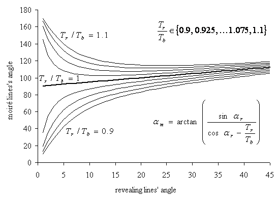
Figure 12. Moiré line inclination as a function of the rotation degree of the revealing layer [xls]
Only for the case when ![]() (the bold curve) the rotation of moiré
lines is linear with respect to the rotation of the revealing layer.
Comparisons of Figure 12 and Figure 11 show the significant difference between
shearing (i.e. inclination of lines) and rotation of the revealing layer
pattern.
(the bold curve) the rotation of moiré
lines is linear with respect to the rotation of the revealing layer.
Comparisons of Figure 12 and Figure 11 show the significant difference between
shearing (i.e. inclination of lines) and rotation of the revealing layer
pattern.
2.3.3. The revealing lines inclination as a function of the superposition image’s lines inclination
From equation (2.6) we can deduce the equation
for computing the revealing layer line inclination ![]() for
a given base layer line inclination
for
a given base layer line inclination ![]() , and a desired
moiré line inclination
, and a desired
moiré line inclination ![]() :
:

The increment of the tangent of the revealing lines’
angle (![]() ) relatively to the tangent of
the base layer lines’ angle can be expressed, as follows:
) relatively to the tangent of
the base layer lines’ angle can be expressed, as follows:

According to equation (2.4), ![]() is the inverse of the optical acceleration
factor, and therefore equation (2.21) can be rewritten as follows:
is the inverse of the optical acceleration
factor, and therefore equation (2.21) can be rewritten as follows:
Equation (2.22) shows that relative to the tangent of the base layer lines’ angle, the increment of the tangent of the revealing layer lines’ angle needs to be smaller than the increment of the tangent of the moiré lines’ angle, by the same factor as the optical speedup.
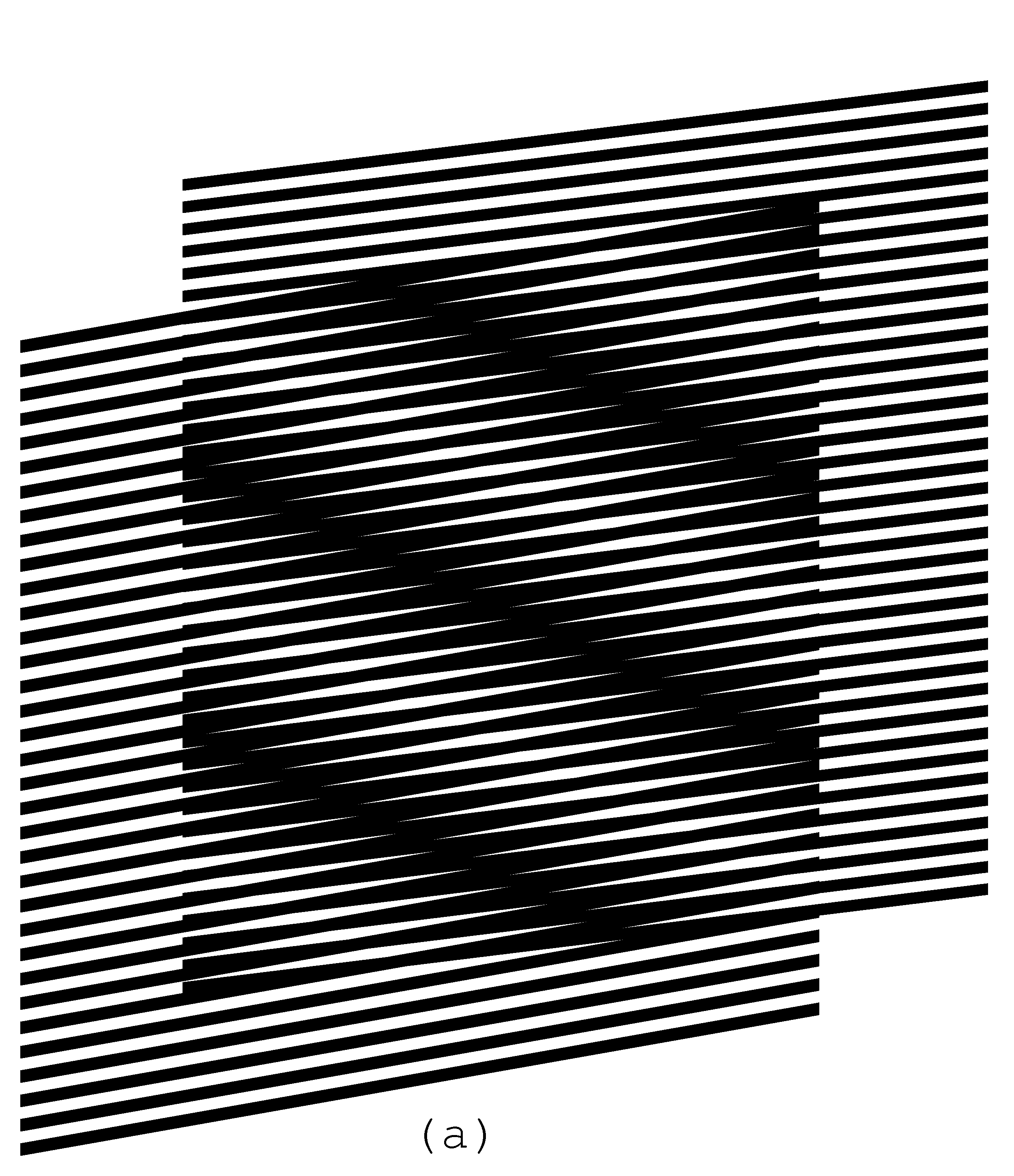
For any given base layer line inclination,
equation (2.20) permits us to obtain a desired moiré line inclination by
properly choosing the revealing layer inclination. In Figure 7 we showed an
example, where the curves of layers follow an identical inclination pattern
forming a superposition image with the same inclination pattern. The
inclination degrees of the layers’ and moiré lines change along the horizontal
axis according the following sequence of alternating degree values (+30, –30,
+30, –30, +30). In Figure 13 we obtained the same superposition pattern as in Figure
7, but the base layer consists of straight lines inclined by –10 degrees. The corresponding
revealing pattern is computed by interpolating the curves into connected
straight lines, where for each position along the horizontal axis, the
revealing line’s inclination angle is computed as a function of ![]() and
and ![]() ,
according to equation (2.20). Figure 13 demonstrates what is already expressed
by equation (2.22): the difference between the inclination patterns of the
revealing layer and the base layer are several times smaller than the
difference between the inclination patterns of moiré lines and the base layer
lines.
,
according to equation (2.20). Figure 13 demonstrates what is already expressed
by equation (2.22): the difference between the inclination patterns of the
revealing layer and the base layer are several times smaller than the
difference between the inclination patterns of moiré lines and the base layer
lines.
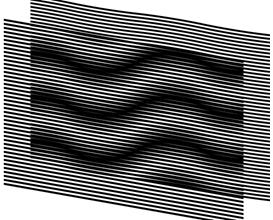
Figure 13. The base layer with inclined straight lines and the revealing layer computed so as to form the desired superposition image [eps], [png]
Another example forming the same superposition pattern as in Figure 7 and Figure 13 is shown in Figure 14. Note that in Figure 14 the desired inclination pattern (+30, –30, +30, –30, +30) is obtained using a base layer with an inverted inclination pattern (–30, +30, –30, +30, –30).
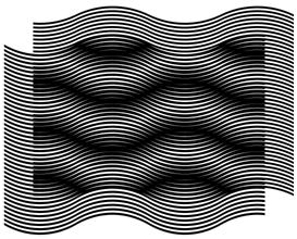
Figure 14. Inversed inclination patterns of moiré and base layer curves [eps], [png]
The GIF animation of Figure 15 shows a superposition image with a constant inclination pattern of moiré lines (+30, –30, +30, –30, +30) for modifying pairs of base and revealing layers. The base layer inclination pattern gradually changes and the revealing layer inclination pattern correspondingly adapts such that the superposition image’s inclination pattern remains the same.
Figure 15. The revealing, base, and superposition images, where the base layer inclination pattern gradually changes, and the revealing layer correspondingly adapts such that the superposition image’s inclination pattern remains the same [ps], [tif], [gif]
3. Superposition of periodic circular patterns
3.1. Superposition of circular periodic patterns with radial lines
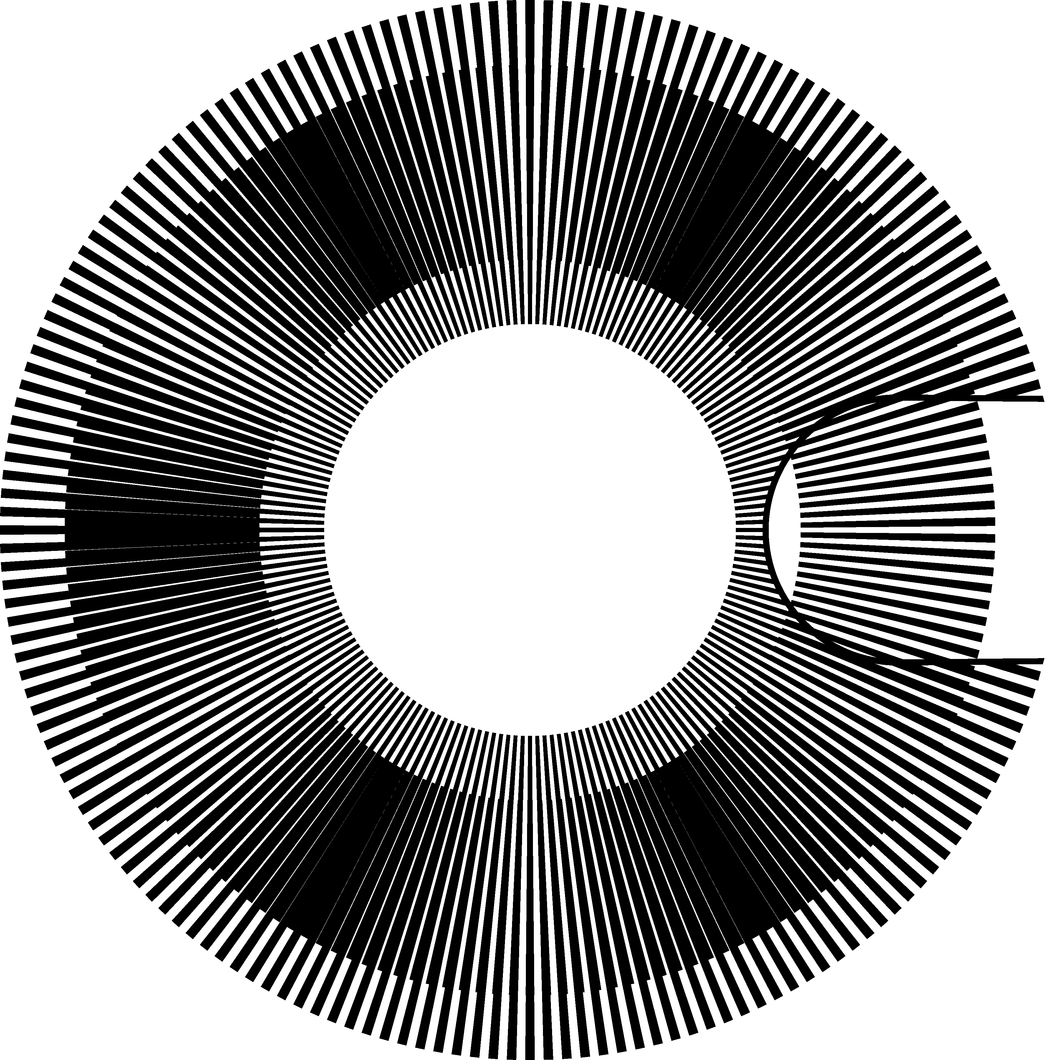
Similarly to layer and moiré patterns comprising parallel lines (see Figure 1, Figure 2, and Figure 3), concentric superposition of dense periodic layer patterns comprising radial lines forms magnified periodic moiré patterns also with radial lines.
Figure 16 is the counterpart of Figure 1, where
the horizontal axis is replaced by the radius and the vertical axis by the
angle. Full circumferences of layer patterns are equally divided by integer
numbers of radial lines. The number of radial lines of the base layer is
denoted as ![]() and the number of radial lines
of the revealing layer is denoted as
and the number of radial lines
of the revealing layer is denoted as ![]() .
.
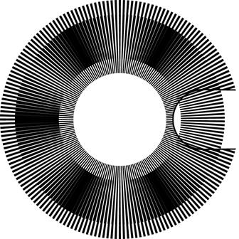
Figure 16. Superposition of two layers with regularly spaced radial segments (a portion of the revealing layer is cut out to show a part of the base layer in the background) [eps], [png]
The periods ![]() and
and
![]() denote the angles between the central radial
axes of adjacent lines. Therefore:
denote the angles between the central radial
axes of adjacent lines. Therefore:
|
|
According to equations (3.1), equation (2.2) can be rewritten as follows:
Therefore the number of moiré radial lines ![]() corresponds to the difference between
the numbers of layer lines:
corresponds to the difference between
the numbers of layer lines:
If in the layer patterns, the full circumferences are divided by integer numbers of layer lines, the circumference of the superposition image is also divided by an integer number of more lines.
The optical speedup factor of equation (2.4) can
be rewritten by replacing the periods![]() and
and ![]() by their expressions from equations (3.1):
by their expressions from equations (3.1):
The values ![]() and
and ![]() represent the angular speeds. The
negative speedup signifies a rotation of the superposition image in a direction
inverse to the rotation of the revealing layer. Considering (3.3),
the absolute value of the optical speedup factor is:
represent the angular speeds. The
negative speedup signifies a rotation of the superposition image in a direction
inverse to the rotation of the revealing layer. Considering (3.3),
the absolute value of the optical speedup factor is:
|
|
(3.5) |

Radial lines have constant angular thickness,
giving them the forms of segments, thick at their outer ends and thin at their
inner ends. The values of ![]() ,
, ![]() , and
, and ![]() do
not depend on the angular thickness of radial lines. In our examples the
angular thicknesses of layer lines are equal to the layer’s half-period, i.e.
the thickness of the base layer lines is equal to
do
not depend on the angular thickness of radial lines. In our examples the
angular thicknesses of layer lines are equal to the layer’s half-period, i.e.
the thickness of the base layer lines is equal to ![]() and
the thickness of the revealing layer lines is
and
the thickness of the revealing layer lines is ![]() .
.
In Figure 16, the number of radial lines of the revealing layer is equal to 180, and the number of radial lines of the base layer is 174. Therefore, according to equations (3.4) and (3.3), the optical speedup is equal to 30, confirmed by the two images (a) and (b) of Figure 17, and the number of moiré lines is equal to 6, confirmed by the image of Figure 16.
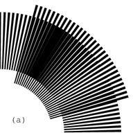
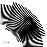
Figure 17. Rotation of the revealing layer by 1 degree in the clockwise direction rotates the optical image by 30 degrees in the same direction [eps (a)], [png (a)], [eps (b)], [png (b)]
Figure 18 shows a GIF animation of the superposition image of Figure 16, where the revealing layer slowly rotates in the clockwise direction.
Figure 18. GIF animation of the superposition image of the layers with periodic radial lines, where the revealing layer slowly rotates clockwise [ps], [tif], [gif]
3.2. Superposition of circular patterns with radial curves
In circular periodic patterns curved radial
lines can be constructed using the same sequences of inclination degrees as
used in section 2.3 for curves of Figure 7. The inclination angle at any point
of the radial curve corresponds to the angle between the curve and the axis of
the radius passing through the current point. Thus inclination angle 0
corresponds to straight radial lines as in Figure 16. With the present notion
of inclination angles for ![]() ,
, ![]() , and
, and ![]() ,
equations (2.6) and (2.20) are applicable for circular patterns without
modifications.
,
equations (2.6) and (2.20) are applicable for circular patterns without
modifications.
Curves can be constructed incrementally with a
constant radial increment equal to ![]() . Figure 19
shows a segment of a curve, marked by a thick line, which has an inclination
angle equal to
. Figure 19
shows a segment of a curve, marked by a thick line, which has an inclination
angle equal to ![]() .
.
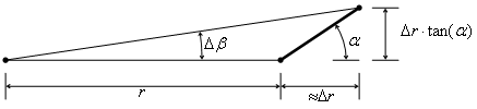
Figure 19. Constructing a curve in a polar coordinate system with a desired inclination
While constructing the curve, the current
angular increment ![]() must be computed so
as to respect the inclination angle
must be computed so
as to respect the inclination angle ![]() :
:
Figure 20 shows a superposition of layers with
curved radial lines. The inclination of curves of both layers follows an
identical pattern corresponding to the following sequence of degrees (+30, –30,
+30, –30, +30). Layer curves are iteratively constructed with increment pairs ![]() computed according to equation (3.6). Since
the inclination patterns of both layers of Figure 20 are identical, the moiré
curves also follow the same pattern.
computed according to equation (3.6). Since
the inclination patterns of both layers of Figure 20 are identical, the moiré
curves also follow the same pattern.
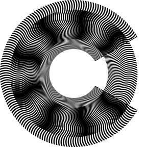
Figure 20. Superposition of layers in a polar coordinate system with identical inclination patterns of curves corresponding to (+30, –30, +30, –30, +30); a portion of the revealing layer is cut away exposing the base layer in the background [eps], [png], multi-page [tif], [gif]
Similarly to examples of Figure 7, Figure 13, and Figure 14, where the same moiré pattern is obtained by superposing different pairs of layer patterns, the circular moiré pattern of Figure 20 can be analogously obtained by superposing other pairs of circular layer patterns. Taking into account equations (3.1), equations (2.6) and (2.20) can be rewritten as follows:
|
|
(3.7) |

Taking into account equation (3.4), equation (3.8) can be also rewritten as follows:

For producing the superposition image of Figure 20, thanks to equations (3.8) and (3.9), other pairs of layer patterns can be created as shown in Figure 21. In the first image (a) of Figure 21, the base layer lines are straight. In the second image (b), the base layer lines inclination pattern is reversed with respect to the moiré lines.
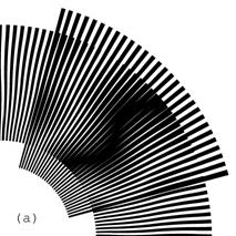

Figure 21. Superposition images with identical inclination pattern (+45, –45, +45, –45, +45) of moiré curves, where in one case the base layer comprise straight radial segments, and in the second case the base layer comprise curves which are the mirrored counterparts of the resulting moiré curves [eps (a)], [png (a)], [eps (b)], [png (b)]
Figure 22 shows an animation, where the moiré curves of the superposition image are always the same, but the inclination pattern of the base layer curves gradually alternates between the following two mirror patterns (+45, –45, +45, –45, +45), and (–45, +45, –45, +45, –45). For each instance of the animation, the revealing layer lines are computed according to equation (3.8) in order to constantly maintain the same moiré pattern.

Figure 22. Animation of the superposition image, where the base layer lines gradually change their inclination pattern from (+45, –45, +45, –45, +45) to (–45, +45, –45, +45, –45) [eps], [tif], [gif]
Equations (3.4) and (3.3) remain valid for patterns with curved radial lines. In Figure 20 there are 180 curves in the revealing layer and 171 curves in the base layer. Therefore optical speedup factor according to equation (3.4) is equal to 20, and the number of moiré curves according to equation (3.3) is equal to 9, as seen in the superposition image of Figure 20.
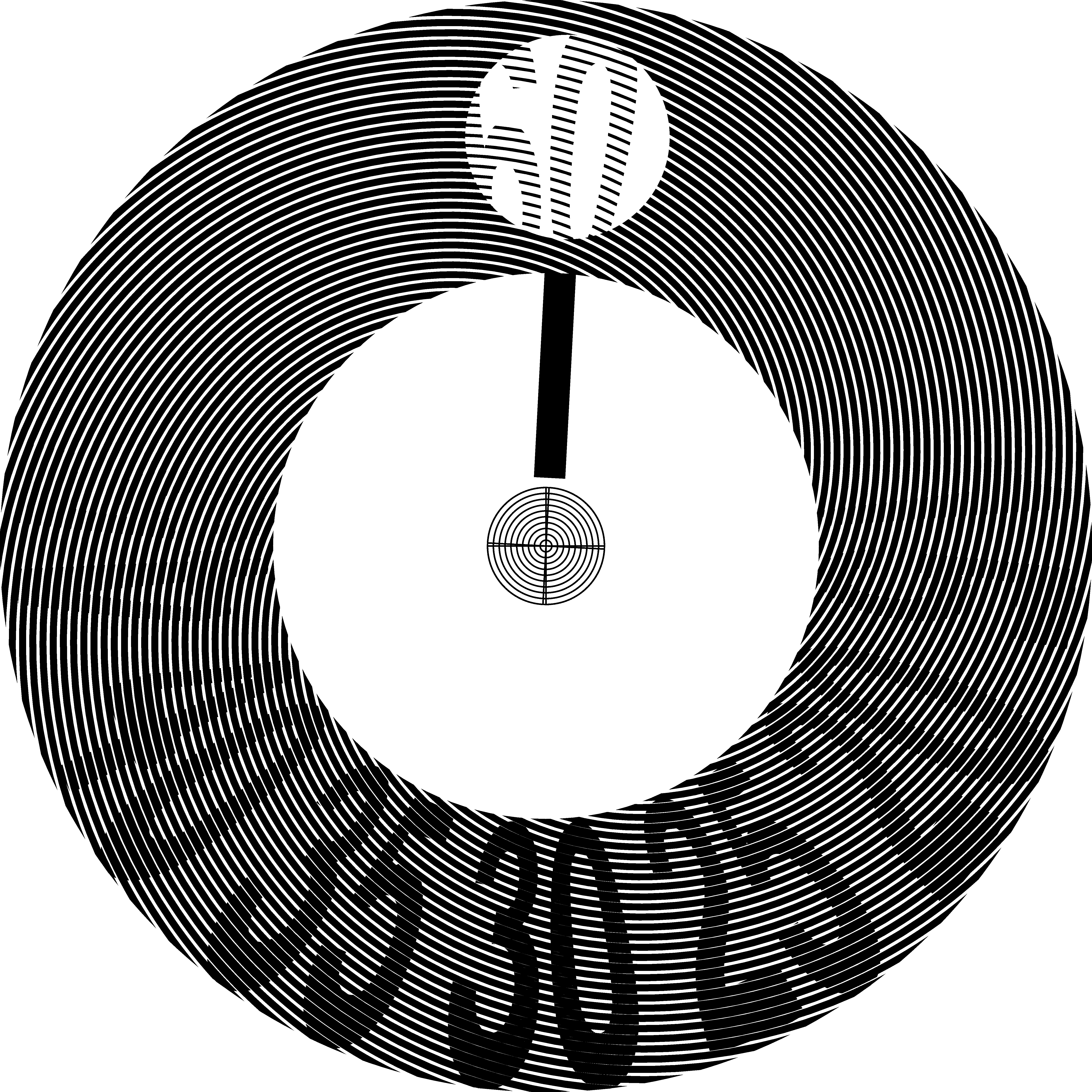
4. Layer patterns with spirals in a single ring
One can form a radial moiré fringe with a period equal to ![]() . In the superposition image of such
pattern we will see only one moiré fringe. This fringe will not have sharp
contours and will appear large and blurred. The radial moiré fringe can be
formed by layer patterns with radial lines or rather radial sectors. For small
speed rations, fine granularity of layer patterns with radial lines cannot be
maintained. As the speed ratio decreases, the superposition image becomes
coarse and the moiré shape becomes visually not identifiable. The fine
granularity can be maintained by using spiral shaped lines in layer patterns.
The layer patterns with spirals can be computed such that the moiré fringe is
kept radially oriented. By reducing the spiral elevation rate in both layers,
sufficiently fine layer patterns can be obtained. However, strongly inclined
spirals resulting to fine patterns make the superposition moiré images less
tolerant to mechanical inaccuracies such as surface deformations of layers or disparities
in concentric superposition of layers.
. In the superposition image of such
pattern we will see only one moiré fringe. This fringe will not have sharp
contours and will appear large and blurred. The radial moiré fringe can be
formed by layer patterns with radial lines or rather radial sectors. For small
speed rations, fine granularity of layer patterns with radial lines cannot be
maintained. As the speed ratio decreases, the superposition image becomes
coarse and the moiré shape becomes visually not identifiable. The fine
granularity can be maintained by using spiral shaped lines in layer patterns.
The layer patterns with spirals can be computed such that the moiré fringe is
kept radially oriented. By reducing the spiral elevation rate in both layers,
sufficiently fine layer patterns can be obtained. However, strongly inclined
spirals resulting to fine patterns make the superposition moiré images less
tolerant to mechanical inaccuracies such as surface deformations of layers or disparities
in concentric superposition of layers.
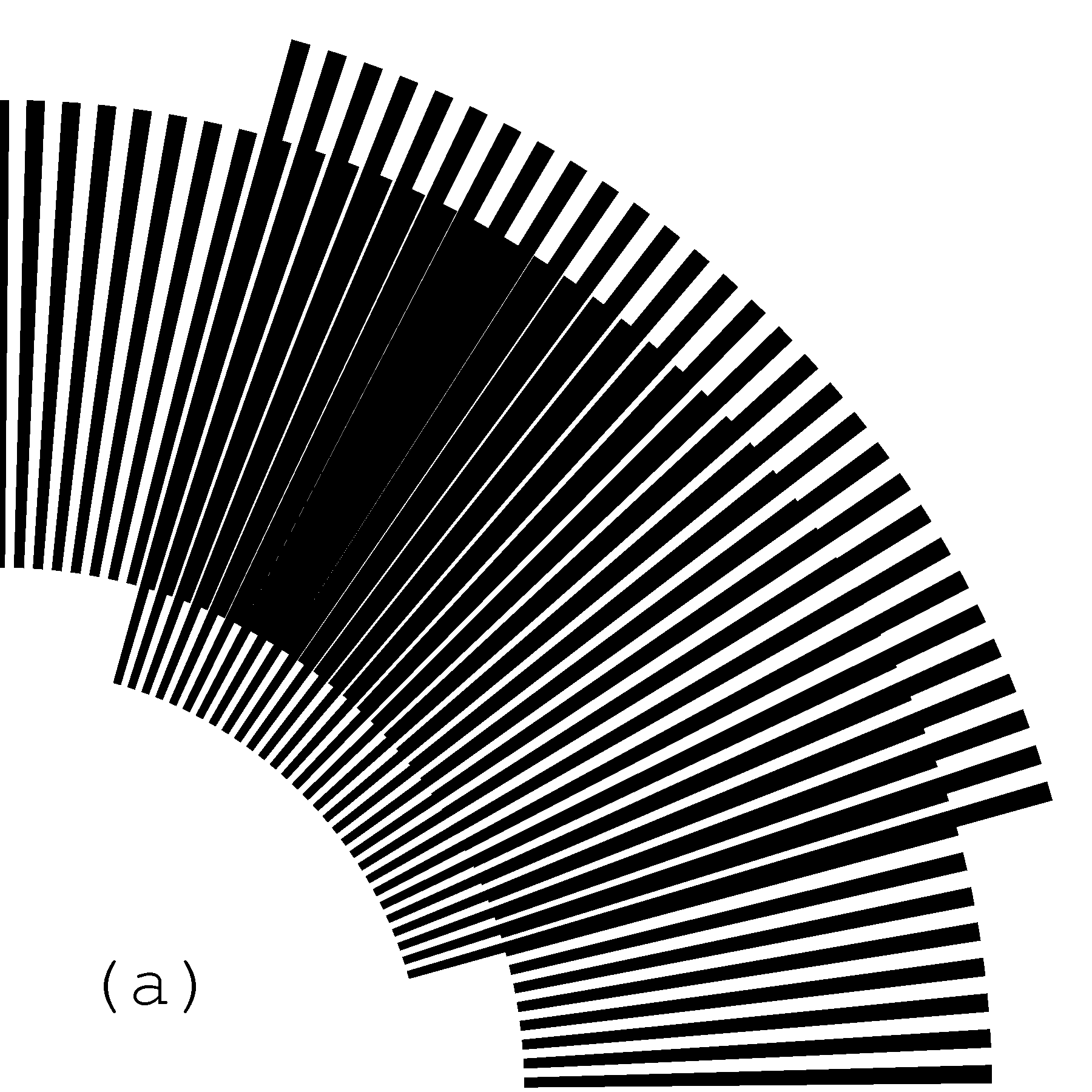
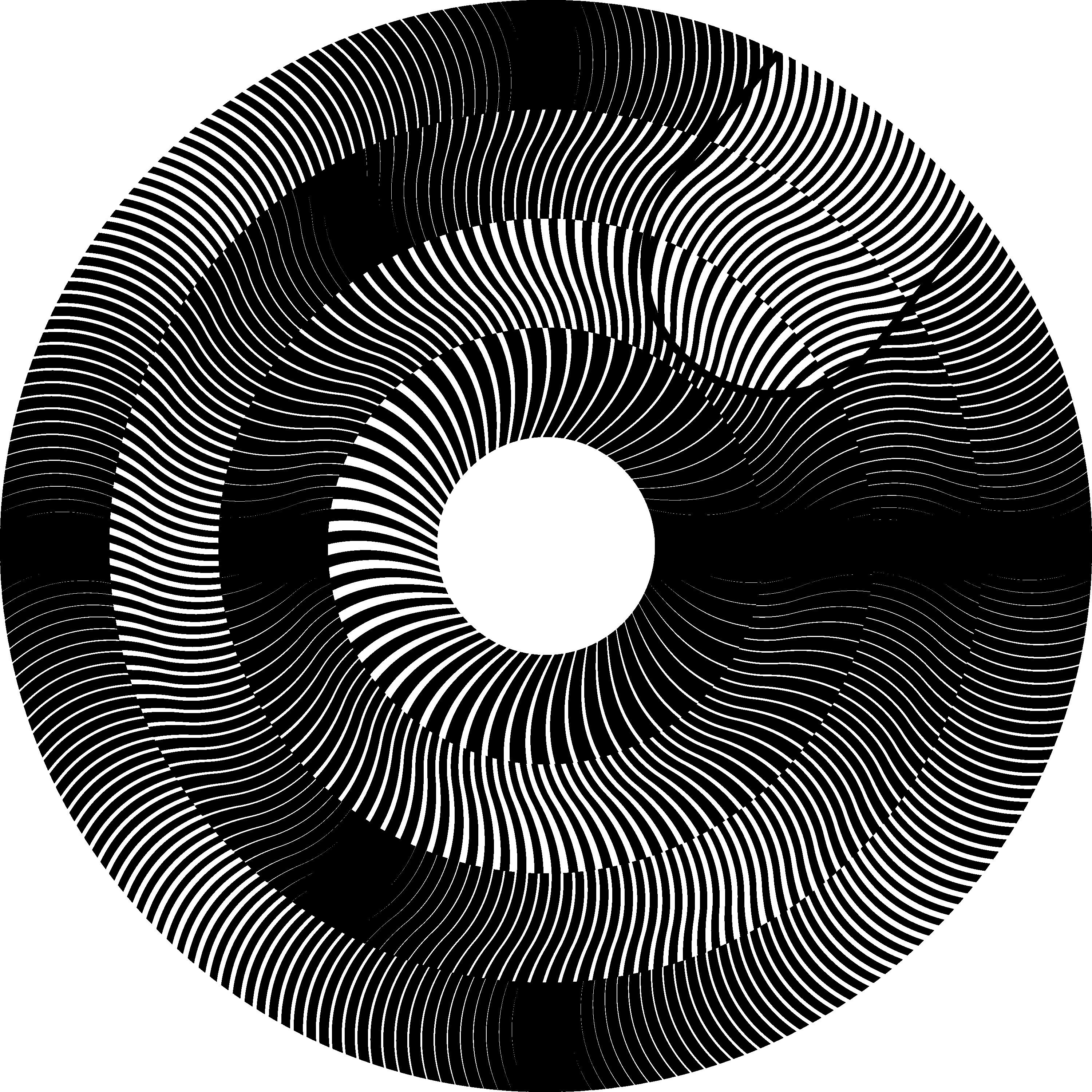
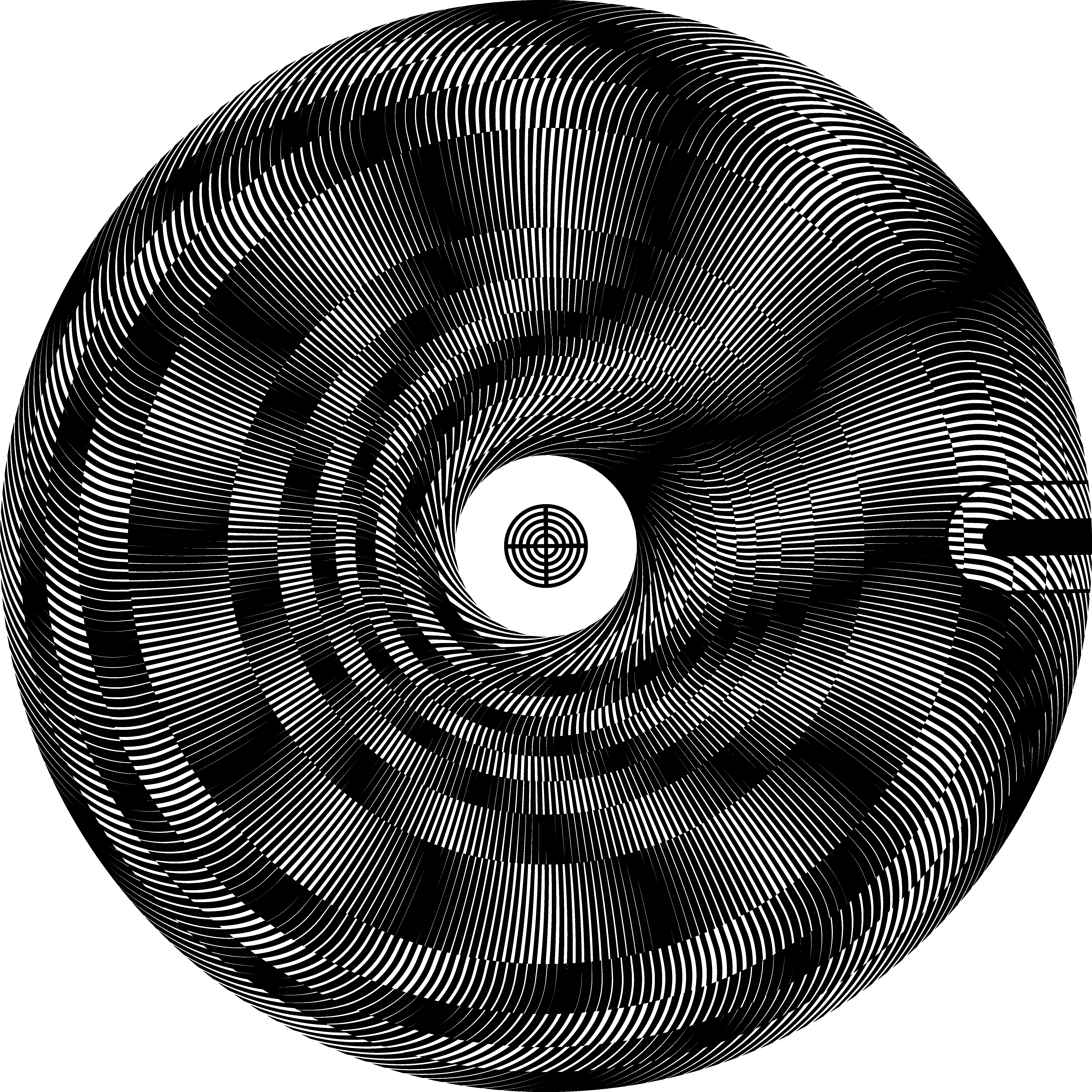
In Figure 23 we show that a design extension of simple spiral patterns with a single moiré fringe may result to a useful application.
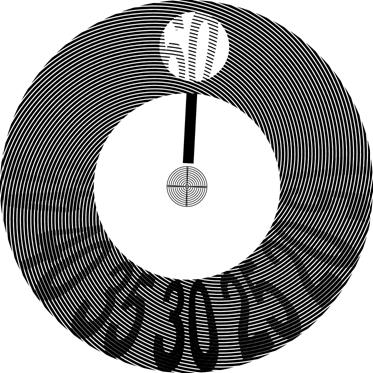
Figure 23. Mono-ring moiré with a speed ratio equal to 60; a single moiré fringe; the spirals of one of the layers are clipped within contours of labels [eps], [png], [gif], [tif]
The example is obtained by taking a simple spiral pattern of a base layer and by cleaning in such pattern all areas lying outside the contours of twelve labels. In such a way, instead of revealing a large and blurred moiré fringe, our superposition pattern reveals more attractive image consisting of labels within the concerned area. The area rotates at a 60 times faster speed than the mechanical rotation speed of the revealing layer. The spirals of two layers are computed so as to produce a moiré fringe with radial orientation.
5. Multi-ring moiré
Refer to equation (3.4) for circular patterns. An optical rotation k times faster than the rotation of the revealing layer can be obtained if:

According to equation (3.3) the number of moiré spots for different values of i:
Therefore, the same moiré speedup factor k
can be obtained with different pairs of revealing and base layer patterns
corresponding to different numbers ![]() of moiré bands.
We can construct several nested concentric circular patterns for the same value
of k and for different values of i.
of moiré bands.
We can construct several nested concentric circular patterns for the same value
of k and for different values of i.
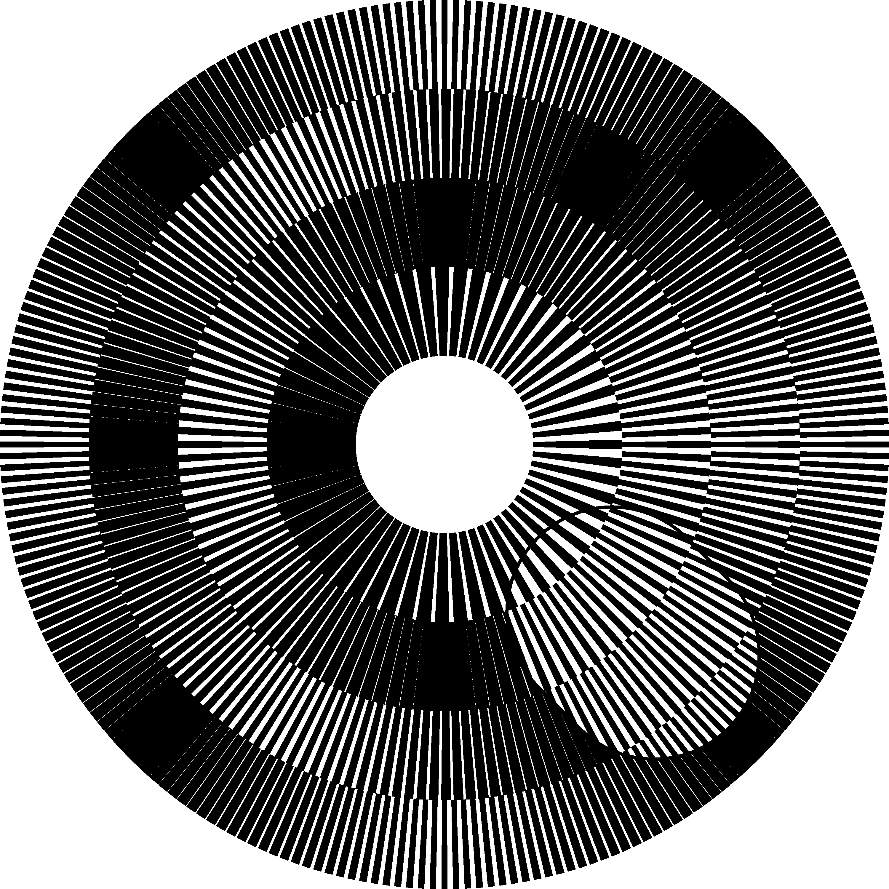
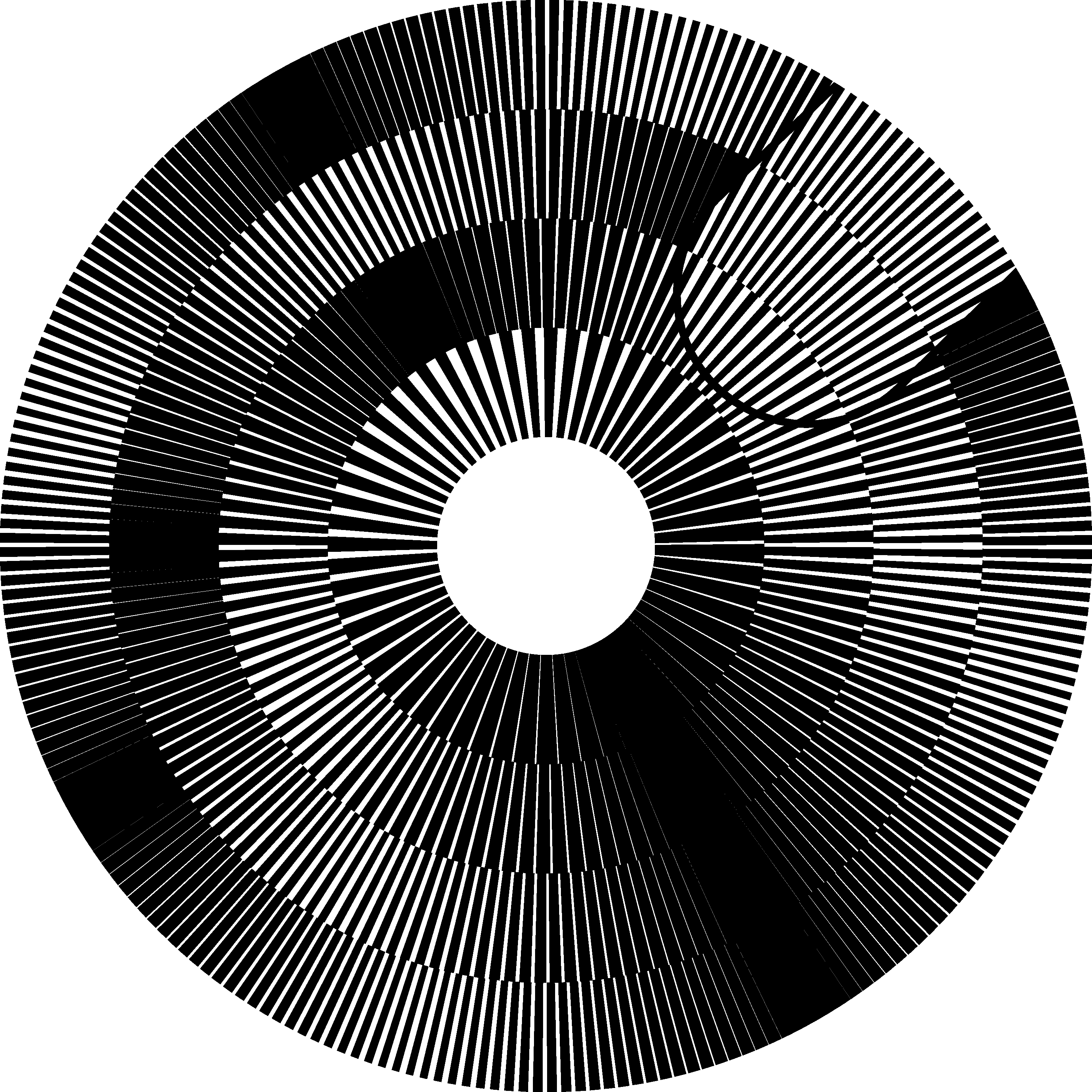
For example, Figure 24 shows four nested adjacent rings, where the value i increments from 1 to 4 when counting from the inner ring toward the outer ring. The number of dark moiré radial lines in each ring changes from 1 to 4. The acceleration factor k is equal to 60. Therefore the revealing layer of the most inner ring has 60 radial lines and the corresponding base layer has 59 lines. Correspondingly the layers of the most outer ring have 240 and 236 radial lines. In Figure 24 a part of the revealing layer is cut out, exposing the base layer. All rings are constructed such that the lines of the revealing and base layers perfectly overlap at the angle zero. Therefore a light moiré radial band appears at the angle zero of each individual rings.
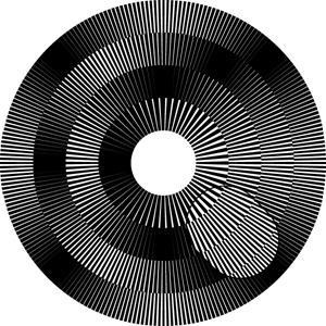
Figure 24. Four nested rings whose layer lines overlap at angle zero [eps], [png]
For the inner ring, the dark moiré band is located at 180 degrees from zero angle zero. The first dark moiré band of the second ring is located at 90 degrees. The first dark moiré band of the third ring is located at 60 degrees and for the most outer ring at 45 degrees.
The patterns of the base and revealing layers of
each ring can be printed so as a dark moiré band appears at the angle zero. For
this purpose, both layer patterns of each ring must be rotated by a degree ![]() :
:
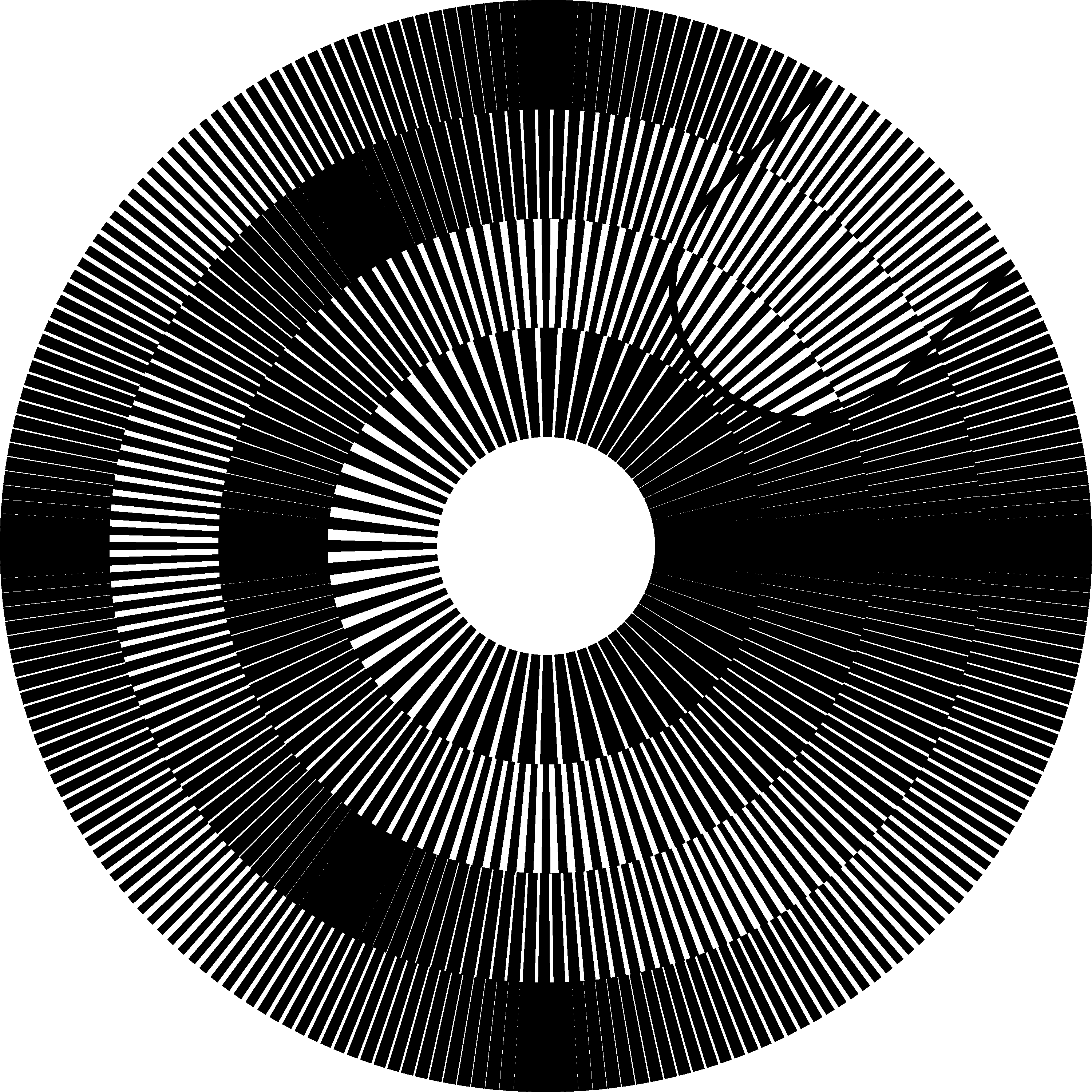
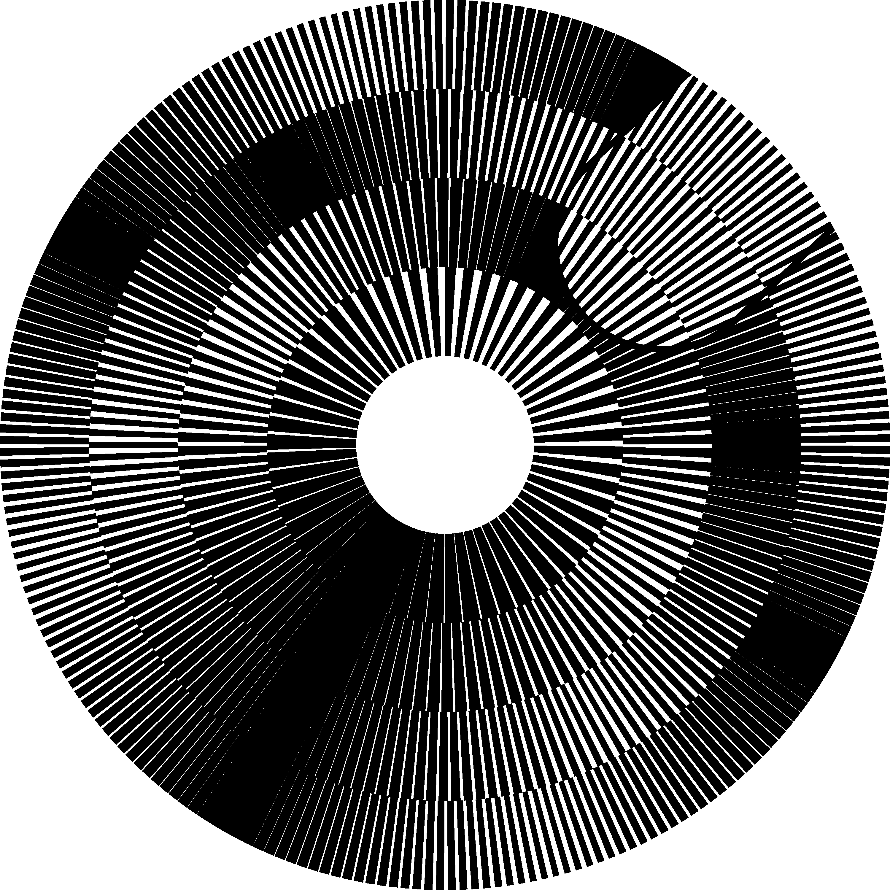
Figure 25 corresponds to the superimposition image of Figure 24, but the ring patterns are constructed according to equation (5.3) such that dark moiré bands appear at the angle zero in all rings. The black moiré bands of all adjacent rings became horizontally aligned forming a joint radial shape.
The index i of the rings, is equal to 1, 2, 3, and 4, counting from the inner ring toward the outer ring. Therefore, according to equation (5.2) the number of moiré spots for the inner ring is equal to 1 and the number of moiré spots of the outer ring is equal to 4, as seen on Figure 25. A part of the revealing layer is cut away exposing the base layer. We consider that the base layer patterns of all rings form a single joint base layer, and the revealing layer patterns of all rings form a joint revealing layer.
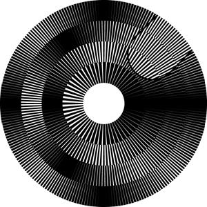
Figure 25. Four nested rings with an acceleration factor equal to 60 for all four rings [eps], [png]
According to equation (5.1), rotation of the revealing layers at a given angular speed must rotate the superimposition image at another angular speed which is identical for all rings. Therefore the radial moiré band traversing all rings will remain aligned all the time during the rotation. Rotation of the revealing layer rotates the optical image at a k times faster speed.
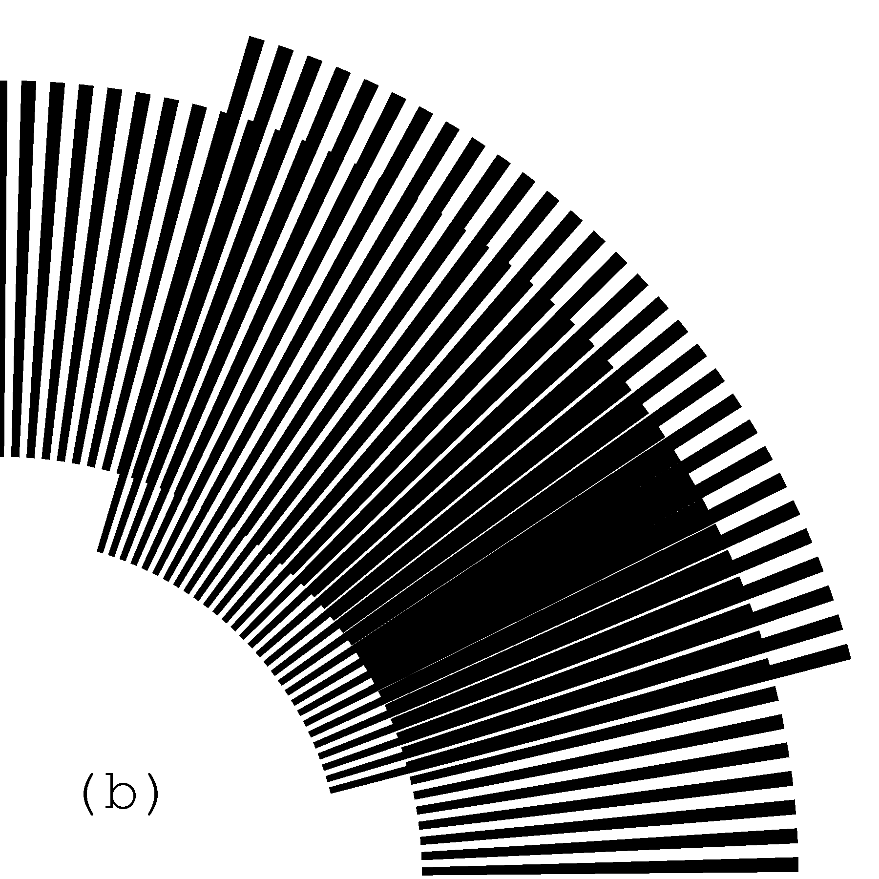
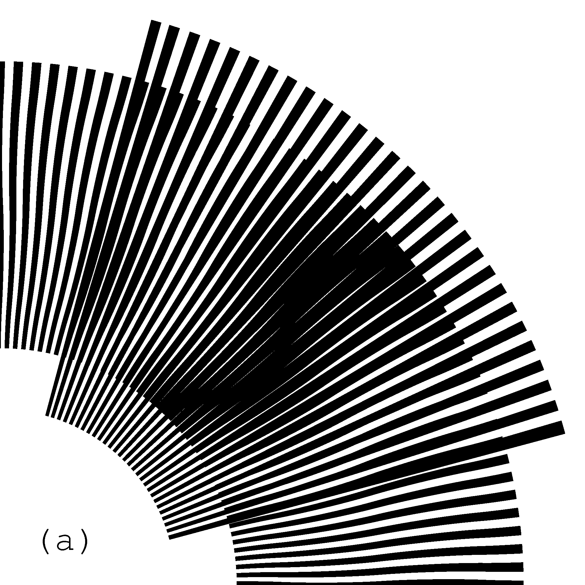
The acceleration factor k of the superimposition image of Figure 25 is equal to 60. Therefore the rotation of the revealing layer by –1 degree rotates the optical image by –60 degrees (compare the image of Figure 25 with the first image of Figure 26). Rotation of the revealing layer by –2 degree rotates the optical image by –120 degrees (compare the image of Figure 25 with the second image of Figure 26). The negative rotation angles correspond to the rotation in clockwise direction. The rotations of the revealing layer in Figure 25 and Figure 26 can be noticed by observing the cut out region of the revealing layer.
 (a)
(a) 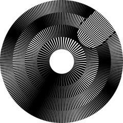 (b)
(b)
Figure 26. Multi-ring moiré for different angles of rotation of the revealing layer [eps (a)], [png (a)], [eps (b)], [png (b)]
The image of Figure 27 animates the superposition image for a slow rotation of the revealing layer by 6 degree in clockwise direction. During this time the superimposition image makes a full rotation of 360 degree.

Figure 27. A GIF animation of the superposition image, when the revealing layer turns by 6 degree in clockwise direction and the superposition image makes one full 360-degree rotation [ps], [tif], [gif]
The superimposition of multi-ring patterns forms a complex moiré image, but at one position a continuous shape is outlined. When rotating the revealing layer, the optical shape rotates without deformations at a k times faster speed.
The widths of the rings of the multi-ring
patterns must not be obligatorily the same. The number ![]() of the ring’s moiré bands also must not necessarily
increment with the ring number. Figure 28 shows a superimposition image with 12
rings, where at the beginning the number of moiré bands increments, but after
reaching a maximal limit at a ring
of the ring’s moiré bands also must not necessarily
increment with the ring number. Figure 28 shows a superimposition image with 12
rings, where at the beginning the number of moiré bands increments, but after
reaching a maximal limit at a ring ![]() , the number
of moiré bands starts decrementing. The maximal number of moiré bands is set to
10. Therefore the number of moiré bands
, the number
of moiré bands starts decrementing. The maximal number of moiré bands is set to
10. Therefore the number of moiré bands ![]() follows
the following sequence (1, 2, 3, … 8, 9, 10, 9, 8). The ring widths are
not constant and are computed so as the largest ring is the ring
follows
the following sequence (1, 2, 3, … 8, 9, 10, 9, 8). The ring widths are
not constant and are computed so as the largest ring is the ring ![]() , at which
, at which ![]() has
its maximal value. The adjacent rings gradually decrease their widths as we
move away from the largest ring.
has
its maximal value. The adjacent rings gradually decrease their widths as we
move away from the largest ring.
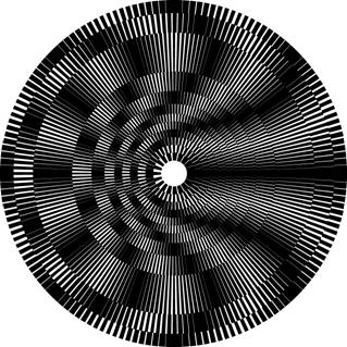
Figure 28. Multi-ring moiré superposition image with variable ring widths [eps], [png]
The width ![]() of
the j-th ring can be computed by equation (5.4), where j is the
sequential number of the ring,
of
the j-th ring can be computed by equation (5.4), where j is the
sequential number of the ring, ![]() is the
number of the widest ring,
is the
number of the widest ring, ![]() is the
minimal ring width, and
is the
minimal ring width, and ![]() is the
maximal ring width.
is the
maximal ring width.

6. Multi-ring moiré with inclined line patterns
6.1. Straight radial moiré lines with curved layer lines
Recall that for measuring the line inclination in circular patterns we use the angle between the line and the radial axis as shown in Figure 19. In Figure 28, inclination of moiré lines of the superposition image is of 0 degree for all rings. The desired degree of moiré inclination can be obtained by different pairs of base and revealing layer patterns, as shown in section 3.2.
It is sufficient to choose for every ring an inclination pattern of the base layer and then, the corresponding inclination pattern of the revealing layer can be computed thanks to equation (3.8) or (3.9). Taking into account that in multi-ring patterns the speedup factor k used in equations (5.1) is the same for all rings, equation (3.9) can be rewritten as follows:
For a particular case, when ![]() , i.e. when we desire straight radial
moiré lines, equation (6.1) is further reduced to:
, i.e. when we desire straight radial
moiré lines, equation (6.1) is further reduced to:
For any inclination of the base layer pattern,
the revealing layer pattern can be computed according to equation (6.2) to
ensure straight radial moiré lines. Figure 29 shows a superposition image with
straight moiré lines, similarly to Figure 25. In contrast to Figure 25 the base
layer lines are not straight. The overall inclination pattern of the entire base
layer across all rings follows the following sequence of inclination degrees ![]() .
.
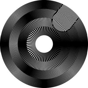
Figure 29. Multi-ring moiré superposition image, where the inclination of moiré lines is of 9 degree and the inclination of the base layer lines follows the following inclination pattern (–30, +30, –30, +30) [eps], [png], [ps], [gif]
Figure 30 is the counterpart of Figure 28. In
both figures the pattern of variable ring widths is computed by equation (5.4).
The inclination pattern of the base layer of Figure 30 (across all rings) corresponds
to ![]() , but the revealing layer line
inclinations are computed so as the superposition image forms the same straight
moiré lines as in Figure 28.
, but the revealing layer line
inclinations are computed so as the superposition image forms the same straight
moiré lines as in Figure 28.
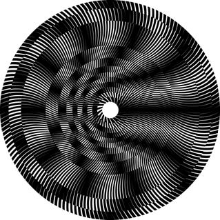
Figure 30. Multi-ring moiré superposition image, where the inclination of moiré lines is of 0 degree and the inclination of the base layer lines follows the following inclination pattern (+30, –30, +30) [eps], [png]
6.2. Curved moiré lines in multi-ring patterns
In Figure 25, Figure 28, Figure 29, and Figure 30 we assemble the base layer and revealing layer patterns from rings rotated according equation (5.3), such that in the superposition image, the moiré fringes are aligned along the angle zero.
Equation (5.3) does not hold for cases when the
moiré fringes themselves are curved. The curved moiré fringes of individual
rings must join into a continuous moiré shape across the multi-ring
superposition pattern. The angle ![]() of equation (5.3)
for every successive ring must be additionally adjusted by the angular shift
gained by the moiré curve while traversing the preceding rings.
of equation (5.3)
for every successive ring must be additionally adjusted by the angular shift
gained by the moiré curve while traversing the preceding rings.
Let ![]() be the
inclination of the moiré line as a function of the radius r. Let
be the
inclination of the moiré line as a function of the radius r. Let ![]() and
and ![]() be
the inner and outer radiuses of the j-th ring. According to equation (3.6)
the angular gain
be
the inner and outer radiuses of the j-th ring. According to equation (3.6)
the angular gain ![]() of the moiré curve
within the j-th ring is expressed as follows:
of the moiré curve
within the j-th ring is expressed as follows:
|
|
(6.3) |

The aggregate angular gain ![]() up to the j-th ring is computed
as follows:
up to the j-th ring is computed
as follows:

Equation (5.3) must be rewritten so as to consider also the adjustment brought by equation (6.4):

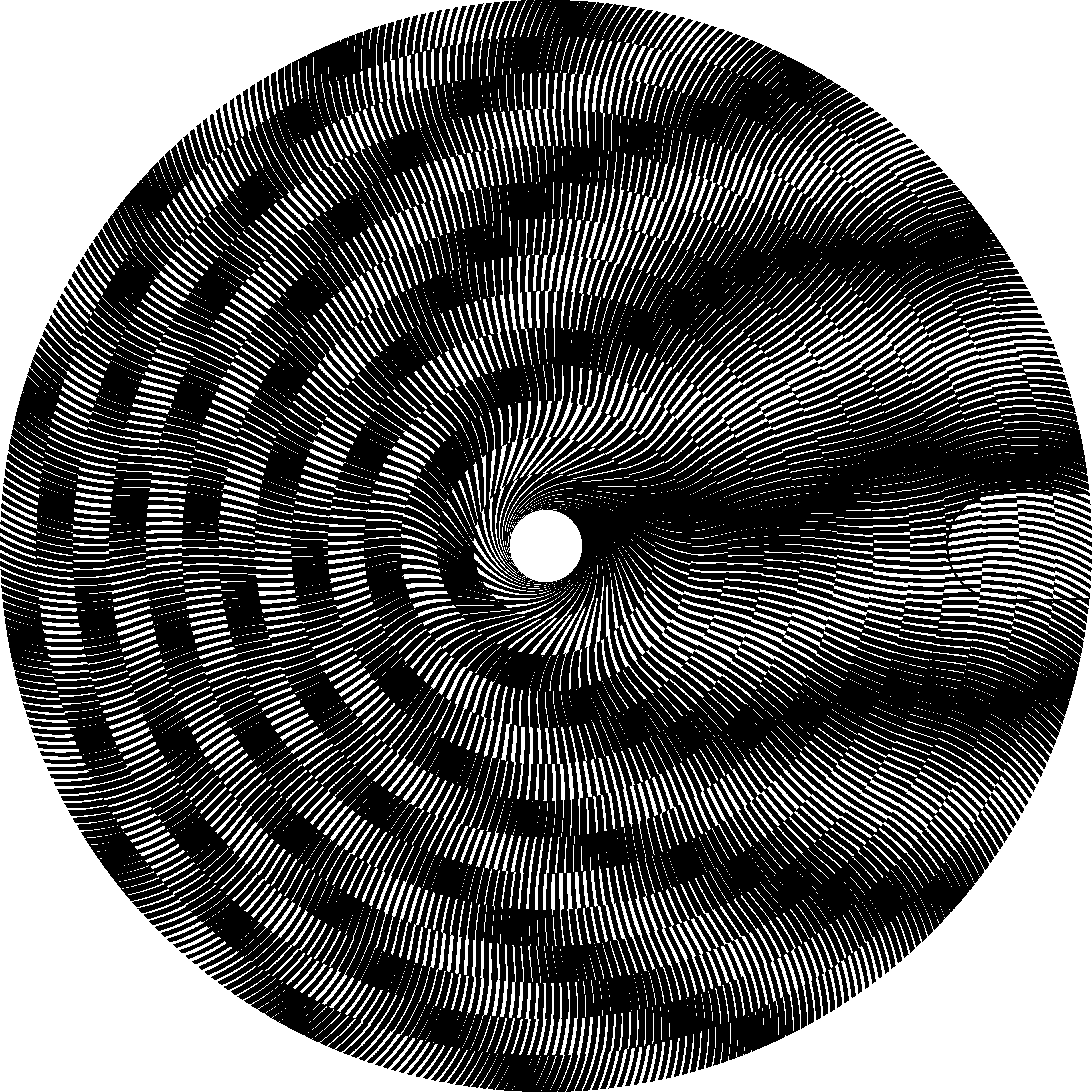
Thanks to the angular adjustments of ring
patterns computed by equation (6.5), in Figure 31 a continuous joint moiré
curve appears across all rings of the multi-ring superposition image. There are
14 rings of equal width. The acceleration factor is equal to k. The
number ![]() of moiré spots increments
starting from 1, for the inner ring, through 14 for the most outer ring. The
base layer line inclination pattern corresponds to the following sequence of
angles (–80, +10, –10, +10, –30). The revealing layer line inclination pattern
is computed according to equation (6.1) so as to ensure the following moiré
inclination pattern (+30, –30, +30, –30, +30). A small part of the revealing
layer is cut away exposing the uncovered part of the base layer pattern.
of moiré spots increments
starting from 1, for the inner ring, through 14 for the most outer ring. The
base layer line inclination pattern corresponds to the following sequence of
angles (–80, +10, –10, +10, –30). The revealing layer line inclination pattern
is computed according to equation (6.1) so as to ensure the following moiré
inclination pattern (+30, –30, +30, –30, +30). A small part of the revealing
layer is cut away exposing the uncovered part of the base layer pattern.
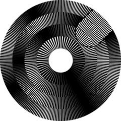
Figure 31. Multi-ring moiré with a continuous serpentine-shaped moiré curve [eps], [png]
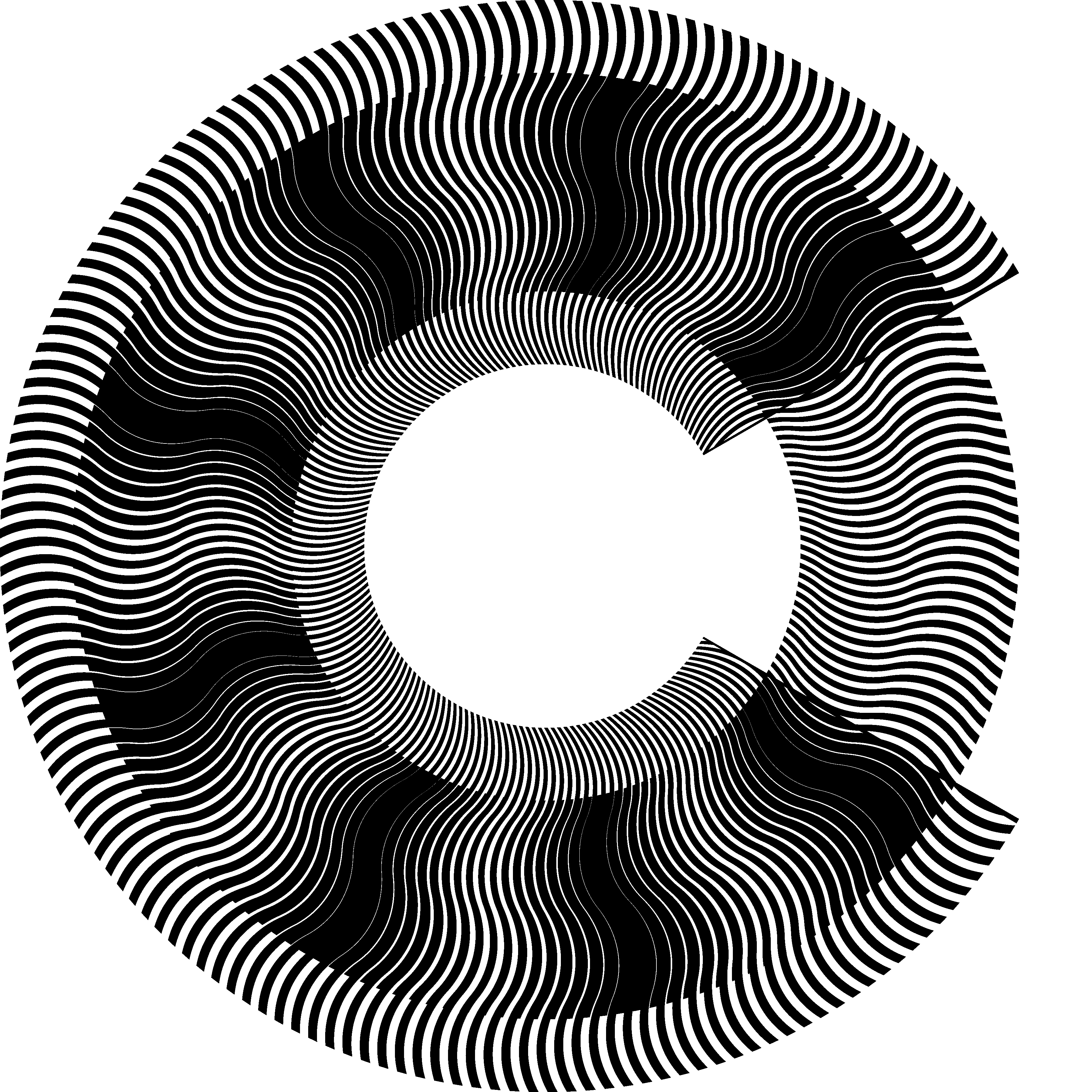
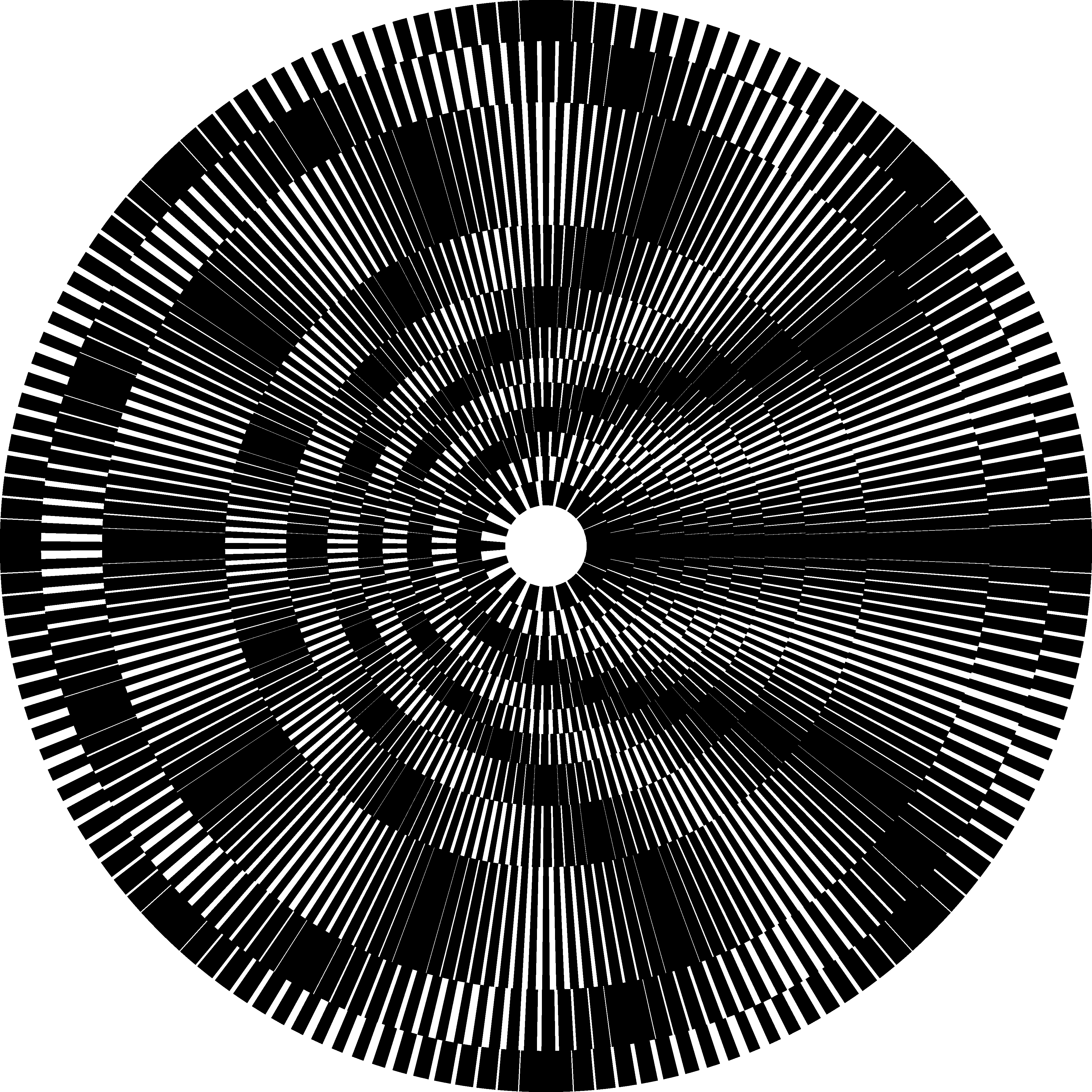
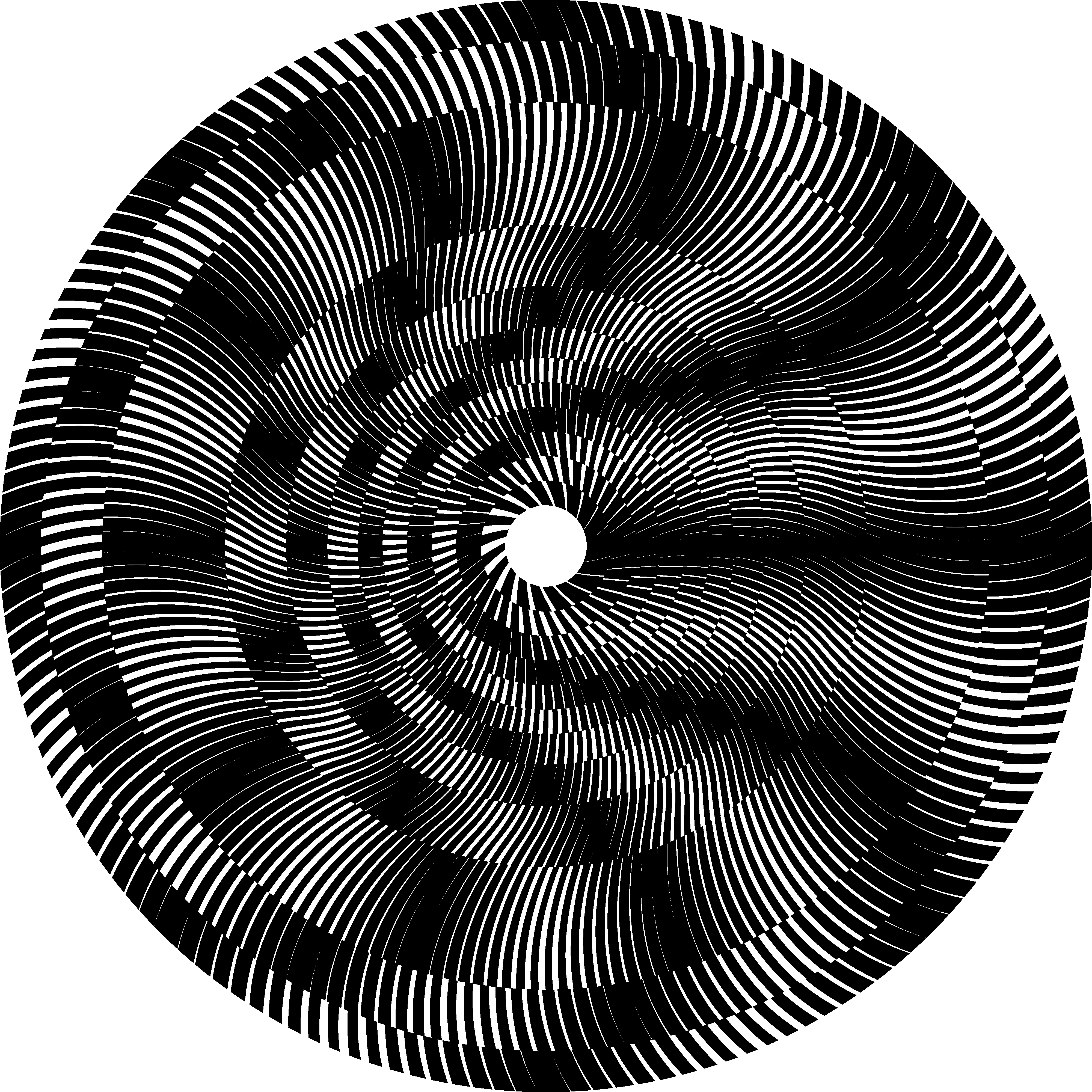
Figure 32 shows a serpentine-shaped moiré curve in a multi-ring moiré with a variable ring width pattern of Figure 28 described by equation (5.4). There are 14 rings; the acceleration factor is equal to 30. The base layer inclination pattern is (–80, 5, 0, –5, –80), the moiré inclination pattern is (30, –30, 30, –30, 30); the revealing layer inclination pattern is computed with equation (6.1).
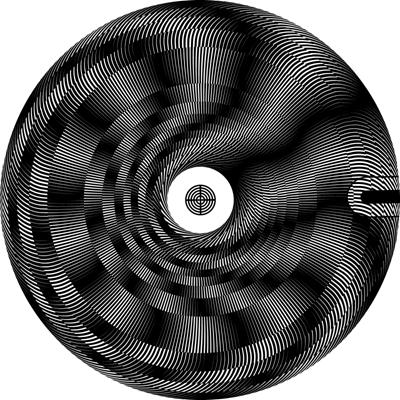
Figure 32. Multi-ring pattern with serpentine-shaped moiré curve and with variable ring width [eps], [png], multi-page [tif], [ps], [gif]
7. Conclusions
Many basic measurement devices comprising one scale and one mechanical pointer have often their developed versions with a supplementary scale with sub-graduations and an auxiliary mechanical pointer which moves faster and aims at increasing the precision of the measured value. A cogwheel type mechanical transmission system is required for a fast movement of the auxiliary pointer in synchronization with the main pointer.
A challenging idea is to employ optical moiré shapes for the auxiliary fast indicator without any mechanical transmission system. Moiré shapes can be obtained by superposition of transparent layers carrying correlated opaque patterns. The following requirements need to be satisfied: (a) the moiré shapes must be sharp, (b) highly periodic moiré shapes cannot be used for indication, (c) the periodicity of moiré shapes must be very long corresponding to the visible window of the superposition image, such that one and only one shape is visible at a time, e.g. in circular moiré the period of moiré shapes must be equal to 360 degree; (d) the optical speedup of the mechanical movement must be linear; (e) the said above must be valid for the full range of mechanical movements of the main pointer which mechanically moves the revealing layer, e.g. in circular patterns for the full range of 360 degree rotation of the revealing layer.
Sharp moiré shapes are easily formed in simple periodic moiré patterns; however their periodicity is very high and cannot be used for indication. Long periods, such as 360 degrees for circular moiré, can be obtained with simple moiré patterns; however the moiré shape becomes blurred and not acceptable for indication. The known random line moiré offers aperiodic shapes. Their shapes are however noisy compared with their periodic counterparts. More importantly the random patterns are completely aperiodic and not offering the required long periodicity.
In this paper we introduced multi-stripe and multi-ring moiré patterns with very long periods suitable for measurement purposes and with moiré shapes as sharp as in highly periodical patterns.
We developed equations for producing straight and curved auxiliary moiré pointer. It is possible to obtain a moiré shape with any desired curve that can be represented by a function. Our equations help to obtain the desired moiré shape for changing base layer patterns by correctly computing the correspondingly matching revealing layer pattern.
The choice of the shape of the moiré fringe must have no impact on the speed factor of the auxiliary moiré pointer. We developed our equations so as to preserve the speedup formulas in their simplest form (2.2), (2.3), and (2.4) regardless the inclination patterns of layers and moiré shapes. The period values p and speed values v, represent the periods and velocities along the axis of the movement of the revealing layer.
8. References
[Amidror00a] Isaac Amidror, The Theory of the Moiré Phenomenon, Kluwer Academic Publisher, 2000 [CH], [US]
[Amidror03a] Isaac Amidror, “Glass patterns in the superposition of random line gratings”, Journal of Optics A: Pure and Applied Optics, pp. 205-215, 28 March 2003 [CH], [US]
[Amidror03b] Isaac Amidror, “Glass patterns as moiré effects: new surprising results”, Optics Letters (Optical Society of America), Vol. 28, Issue 1, pp. 7-9, 1 January 2003 [CH], [US], [epfl]
[Glass69a] Leon Glass, “Moiré Effect from Random Dots”, Nature 223, pp. 578-580, 1969 [CH], [US], [Nature]
[Glass73a] Leon Glass and Rafael Pérez, “Perception of Random Dot Interference Patterns”, Nature 246, pp. 360-362, 7 December 1973, [CH], [US], [ca]
[Hutley99] M.C. Hutley and R.F. Stevens, “Optical inspection of arrays and periodic structures using moire magnification”, IEE Colloquium: Microengineering in Optics and Optoelectronics, No. 187, p. 8, 16 November 1999
[Kamal98] Hala Kamal, Reinhard Völkel, and Javier Alda, “Properties of moiré magnifiers”, Optical Engineering 37 (11), pp. 3007-3014, November 1998 [CH], [US]
[Morse61a] Stanley Morse, August J. Durelli, and Cesar A. Sciammarella, “Geometry of moiré fringes in strain analysis”, American Society of Civil Engineers, Vol. 126, Part I, pp. 250-271, 1961 [CH], [US]
[Nishijima64a] Y. Nishijima and G. Oster, “Moiré patterns: their application to refractive index and refractive index gradient measurements”, Journal of the Optical Society of America, Vol. 54, No. 1, pp. 1-5, January 1964 [CH], [US]
[Oster63a] G. Oster and Y. Nishijima, “Moiré patterns”, Scientific American, Vol. 208, pp. 54-63, May 1963
[Sciammarella62a] C. A. Sciammarella and A. J. Durelli, “Moiré fringes as a means of analyzing strains”, American Society of Civil Engineers, Vol. 127, Part I, pp. 582-587, 1962 [CH], [US]
Formats [doc 7.12MB], [htm], [pdf 1.05MB]